 فارسی
فارسی  Arabic
  Russian
In addition to scrap analysis, the materials used for molding and assembly are also inspected.
The melting department continuously sends samples to the laboratory for analysis and receives the analysis results in the shortest possible time to adjust the chemical composition of the melt. Further details about the quantometer device will be discussed later.

The hardness of produced parts, as one of the most important mechanical properties of wear-resistant parts, is always under control. Due to the large size of cast parts, a portable hardness tester is used to measure hardness. Additionally, the microstructure of the produced products is examined using available metallographic equipment, and imaging and archiving of the microstructure samples are possible as one of the control factors.
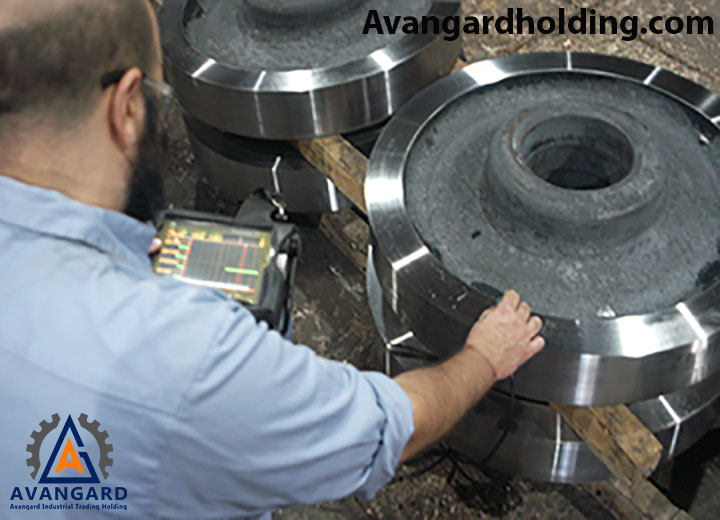
Another activity of the quality control laboratory in approving produced parts is conducting ultrasonic testing and other common tests in the casting industry to ensure the absence of internal defects. We will discuss these common tests in more detail later.
Types of Applied Tests at Avangard Company:- Chemical Analysis (Quantometer)
- Metallography and Structure Determination
- Hardness Testing
- Liquid Penetrant Testing (PT)
- Magnetic Particle Testing (MT)
- Ultrasonic Testing (UT)
- Radiographic Testing (RT)
- Mechanical Properties Testing (Tensile Testing, Impact Testing, etc.)
Avangard Company, as one of the producers and suppliers in the casting industry, has set its mission to meet legal requirements and specific customer needs, aiming to achieve customer satisfaction and trust. In this direction, the company pursues the following main objectives:
- Striving to enhance product quality and continuously improve quality to increase customer satisfaction, which is the primary goal of the organization.
- Reducing costs and production waste by relatively increasing efficiency.
- Focusing on the training system as a tool to enhance the technical and cultural capabilities of personnel.
- Delivering products to customers on time.
Tools and equipment in this field essentially form the infrastructure of a control and automation system. They include instruments such as various controllers, indicators, transmitters, recorders, and more. These tools are responsible for accurately measuring, transmitting, displaying, recording, and controlling critical physical parameters such as temperature, pressure, flow, liquid level, dimensions, and more in industrial processes.
Tape measures are one of the most widely used measuring tools in various industries. Unlike tools such as micrometers and calipers, tape measures do not have very high precision, but they can measure large ranges with acceptable accuracy relative to their measurement range. Generally, tape measures are divided into two types based on their measurement method: laser and simple.

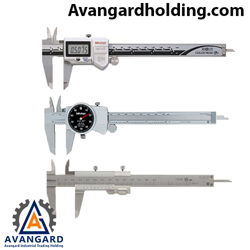
A caliper is a high-precision measuring tool widely used in various industries. It can be considered the right hand of engineers in different fields. Calipers have jaws that allow for the measurement of various dimensions of objects, such as internal and external diameters, length, thickness, and depth. Generally, calipers are divided into three types based on their reading method: vernier, digital, and dial. One of the main reasons for using calipers is their high precision. The measurement accuracy of vernier calipers is determined by dividing one by the number of divisions on the vernier scale. The measurement accuracy of commonly used calipers in the industry is approximately up to 0.01 millimeters.
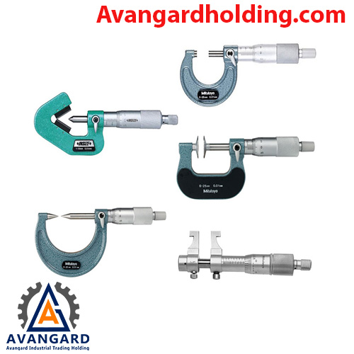
Another type of precision measuring tool is the micrometer, which offers very high measurement accuracy. For this reason, when calipers are not precise enough, micrometers can be used to measure internal, external, height, and thickness dimensions of certain parts. The accuracy of micrometers typically reaches 0.001 millimeters. Micrometers also come in two types: analog and digital. In the digital model, the measured value is easily visible on the display, while the analog type has its own specific method for reading the measured value.
In micrometers, the force applied to the jaws and the workpiece is controlled by a ratchet system. This is in contrast to the reading method of vernier calipers, where the force applied by the jaws to the workpiece is not controlled. This means that when the force on the workpiece reaches a certain level, the ratchet handle spins freely, which enhances the accuracy of the measurement.
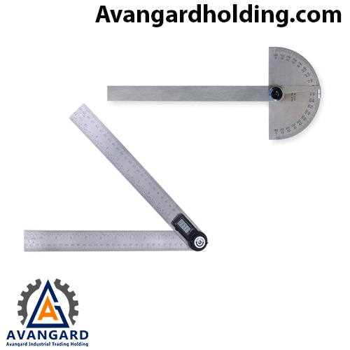
A protractor is a specialized tool for measuring various angles of objects and is widely used in different professions. One of its applications is determining cutting angles, especially in beveling parts. Protractors come in two types: analog and digital. The analog protractor consists of a protractor and a ruler connected together, and by placing the object between them, the angle can be read directly from the protractor. In the digital type, two rulers are connected via a hinge, and the angle between them can be easily read using a digital display.
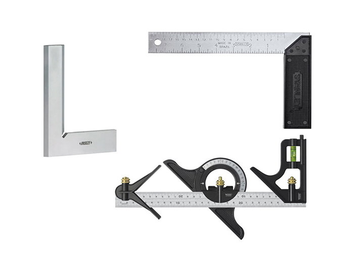
A square is a rigid measuring tool used to determine a 90-degree angle and to check the perpendicularity of two parts. Squares are produced with different levels of precision and in various sizes. Blade squares, carpenter squares, and combination squares are examples of widely used types in the industry. The blade square is the most precise type of square, made with high accuracy from stainless steel, and is used in professions such as machining where high precision is required. Carpenter squares are larger in size compared to blade squares but have lower precision and consist of a ruler and a base. The combination square, or three-piece square, is a versatile measuring tool that can be used not only as a square but also as a protractor, ruler, level, and center finder.
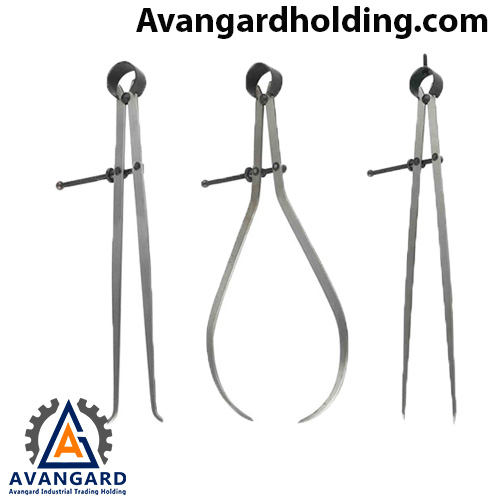
Industrial compasses are one of the types of compasses used for performing many tasks such as measurement, marking, gauging the ratio of two parts, ruling, finding the center of a circle, drawing circles, finding lines perpendicular to a circle, and many other tasks used in industrial geometry. There are various types of industrial compasses used in industries such as engineering and drafting, among others. Some of these types include straight industrial compasses, inside caliper industrial compasses, outside caliper industrial compasses, graduated industrial compasses, dial industrial compasses, digital industrial compasses, divider industrial compasses, and micrometer industrial compasses.
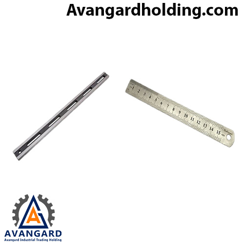
The industrial ruler is another measuring tool used for drawing lines, measuring parts, or for surface control on flat tables. Industrial rulers are designed for industrial environments, so they are highly durable and are usually made of stainless steel, making them resistant to wear and corrosion.
Types of RulersRulers come in various types, which include:
Simple Ruler: The graduated edges of this ruler are used for measurement and marking.
Feeler Ruler: This ruler is used for measuring edge flatness and determining flatness levels with the help of a feeler gauge.
Digital Ruler: Another type of ruler used when speed and measurement accuracy are important.
Contour Ruler: This ruler is used for measuring inaccessible and difficult angles in the wood industry and for modeling cast parts.
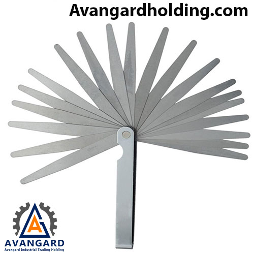
A feeler gauge refers to a set of several small metal blades, each of which is made to a specific thickness and surface standard. These blades are inserted into the gap between a metal ruler and the surface of the workpiece based on the distance between the two tangent surfaces. Depending on the size of the gap and the thickness of the feeler gauge blade, it indicates the distance between the ruler and the workpiece or, in other words, determines the level of flatness.
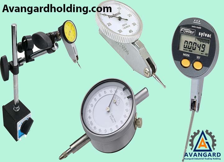
The dial indicator or measuring clock is one of the most widely used types of precision measuring tools. It is used for measuring the surface difference of one or two parts, coupling and aligning two shafts or parts, or checking the flatness and levelness of a part, among other applications.
It is widely used in various sectors of the industry and comes in different types such as test indicators, dial indicators, and digital dial indicators available in the market.
The dial indicator is a highly precise measuring tool used in both light and heavy industries. The reason for this name is its strong resemblance to analog clocks. The primary reason for its use is its measurement accuracy, which typically ranges between 0.01 and 0.001 millimeters, depending entirely on the model and the manufacturer.
The level is one of the types of hand tools that is widely used in the molding process in casting. This tool is used to control the slope of a surface and determine whether surfaces are horizontal or vertical. It is worth noting that today, various levels with different capabilities have been designed and produced. Some levels, in addition to controlling slope, can also measure different angles. Levels are generally divided into two categories: graduated and non-graduated. It should also be mentioned that digital and laser levels have now entered the market.

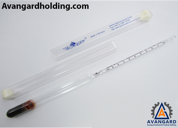
The Baumé is a device for measuring density, invented by the French pharmacist Antoine Baumé in 1768 to measure the density of various liquids. The Baumé scale (B) is a unit for measuring the relative density of liquids (the density of liquids relative to the density of water), and the unit of the Baumé hydrometer is in percentage. The laboratory Baumé is a simple tool for controlling and measuring the density or specific gravity of a solution. The laboratory Baumé consists of a floating cylinder with a conical and heavy lower end and a narrow tubular upper end. When the laboratory Baumé is placed in a liquid, it will assume a vertical position and sink into the liquid. The extent to which it sinks is related to the density of the liquid. The operation of the laboratory Baumé is based on Archimedes’ principle, which states that a solid suspended in a fluid is buoyed up by a force equal to the weight of the fluid displaced.
In the quality control unit of Avangard, this tool is used to control raw materials for casting, such as mold coating (mold paint), industrial alcohol, sodium silicate adhesive, and more.
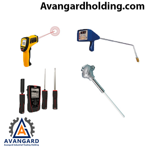
A thermometer is a device that measures temperature based on units such as Celsius, Fahrenheit, Kelvin, and Rankine.
The types of thermometers vary across different industries. Here, we will introduce the thermometers used in the steel, melting, and casting industries.
The temperature of molten metal must be within a specific range required by the metallurgy and quality control departments. Determining the temperature of the molten metal when it reaches the molten state in the melting furnace and during pouring is crucial for both traditional and scientific foundry workers. Not knowing the melting temperature and its abnormal increase can lead to numerous problems, such as the loss of certain elements, reduced furnace lining lifespan, and even mold deformation. Similarly, not knowing when the molten metal temperature is too low can cause issues such as metal solidification in the ladle or mold channels, incomplete filling of the mold, and more. Therefore, knowing the correct temperature of the molten metal is one of the most important pieces of information for a foundry worker.
Among the known methods for measuring molten metal temperature, two main methods are identified: non-contact methods (laser or pyrometric/optical methods) and contact thermometers. Among these, contact thermometers for molten metal temperature offer high accuracy. Additionally, in the quality control unit of Avangard, non-contact thermometers (laser or pyrometric methods) are also used to control the temperature of parts during mold release or heat treatment furnace temperature, among other applications.
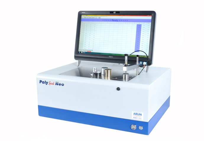
Quantometer is a device used to measure the percentage of various elements present in a part. The optical spectrometer or quantometer is one of the precise analysis systems for measuring elements in metals, capable of analyzing alloys with high accuracy and determining all alloying elements in a sample. The process involves preparing the surface of the part to be tested, ensuring it is completely smooth and free of any contamination or grease. The sample is then placed on the area where the spark will be generated. The mechanism of this test is based on optical emission. The sample material is vaporized by an electrical discharge, and the atoms and ions formed from the vaporized atoms are excited and emit radiation. Then, based on the wavelength range of the emitted light for each element, the most accurate emission line is selected to measure the concentration of that element in the sample.
In most quantometers, due to limitations in sample placement, it is not possible to analyze samples of any size. Samples must be prepared in specific dimensions for testing. It is worth noting that the results from these devices are more accurate compared to portable devices that perform spark testing on parts in open spaces. Spark refers to the spark generated by the quantometer’s electrode on the surface of the part, allowing the device to determine the elements present in the part based on predefined wavelengths.
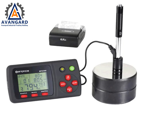
Hardness testing refers to the measurement of how deeply a hard indenter penetrates the surface of a metal or other material. This is performed using various hardness testers, which use different units such as Rockwell, Brinell, Vickers, and others. For measuring the hardness of metals, the Rockwell unit is most commonly used, denoted by the symbol HRC. In the casting industry, Rockwell is also predominantly used to express the hardness of steels.
Hardness testers are generally divided into two types: portable hardness testers, which can be easily held in hand and placed on the metal to measure its hardness, and larger, non-portable testers, which require the metal or steel part to be placed underneath for measurement. The latter type is more commonly used in industrial laboratory settings.
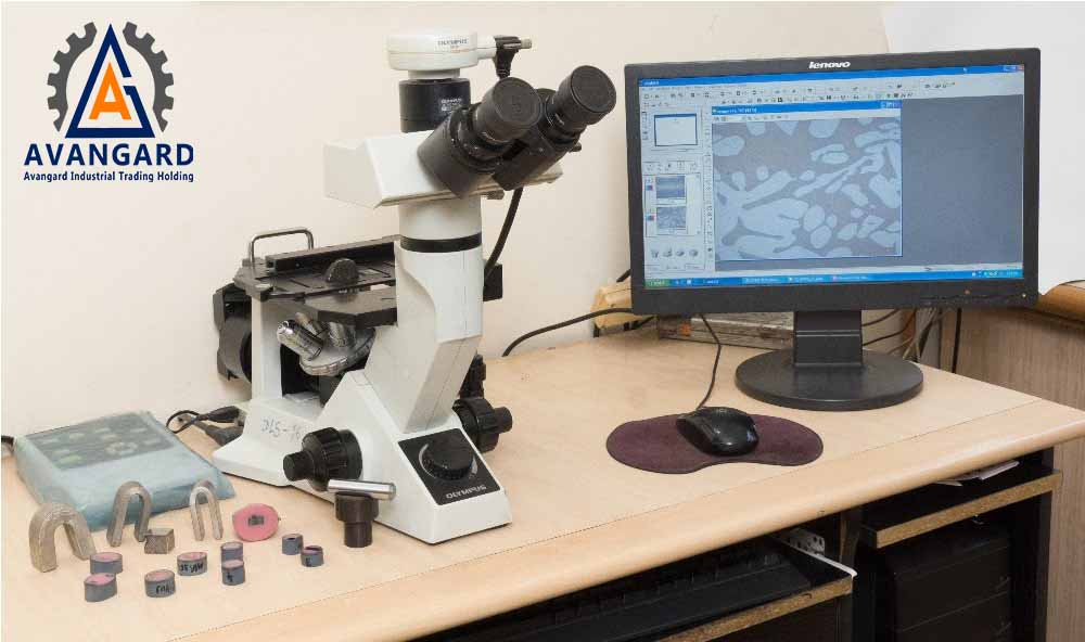
Metallography refers to the science and art of preparing metal samples and examining their microscopic microstructure. In many materials, the grains that make up their structure are microscopic in size, typically on the order of microns, and their components must be observed and analyzed using microscopes. However, the challenge is not just magnification. The surface of the microstructure must also be prepared. In microscopic examinations, only the external surface of objects is analyzed, so a very smooth and mirror-like surface is required to reveal the important components of the microstructure. The set of activities that lead to the preparation of such a surface and the microscopic examination of the microstructure is called metallography. Metallography refers to the study and analysis of the internal microstructure of metals. Metallography quickly established itself as one of the fundamental principles of materials science and engineering in the field of metallurgy. Today, without understanding the modern principles of metallography and optimizing its use, industrial, research, and quality control activities would face significant challenges. Examining the micro- and macro-structure of metals using optical and electron microscopes, comparing them with established standards, and predicting physical and mechanical properties, as well as analyzing structural and surface defects, are made possible. This is a critical aspect of the casting industry, and the engineering team at Avangard has complete mastery of metallography.
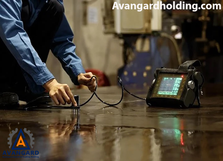
Ultrasonic Testing (UT) is a non-destructive method widely used for inspecting internal defects in various parts, especially cast components. UT testing is utilized across all major industries and is particularly useful for detailed inspection of cast parts, welded joints, and other applications. Ultrasonic testing is employed to detect internal defects such as shrinkage cavities, cracks, and porosity. In this mechanism, high-frequency ultrasonic waves are directed onto the part using a sound generator. These waves reflect upon encountering subsurface defects in the material. The reflected waves are then captured by a sound receiver and converted into electrical pulses. Finally, these pulses are displayed as clear signals on a screen. By analyzing these signals, the operator can determine various details such as the location, size, depth, and type of defect in the part.
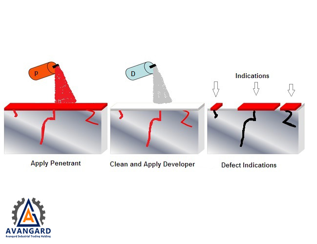
Liquid Penetrant Testing (PT) is another type of Non-Destructive Testing (NDT) used to detect and identify surface defects as well as subsurface defects that are open to the surface. PT testing is the best method for inspecting various surface cracks, porosity, laminations, lack of fusion in welds, open edges, and any leaks in cast components. Today, PT testing is successfully used in various industries. This test is effectively performed on ferrous and non-ferrous metals, ceramics, powder metallurgy parts, welded components, glass, and some plastics. For PT testing, three types of sprays are required:
1- Cleaner/Remover Spray
2- Penetrant Spray
3- Developer Spray
In PT testing, the liquid penetrant is applied to the surface of the object for a specified period. Due to capillary action, the penetrant seeps into any open surface defects. The excess liquid is then removed from the surface. The surface is dried, and the developer is applied, which draws out the penetrant from the defects, revealing the size, location, and nature of any discontinuities present. Thus, PT testing is performed by observing the surface of the part and noting the color contrast between the residual penetrant drawn out from the defect and the surface of the part.
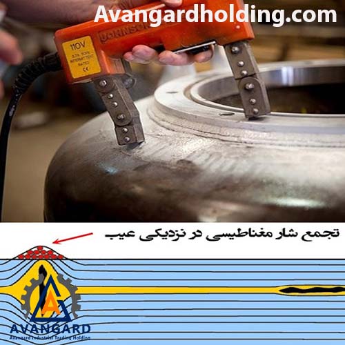
Magnetic Particle Testing (MT), which stands for Magnetic Particle Test, and sometimes referred to as Magnetic Particle Inspection (MPI), is a non-destructive testing (NDT) method. It is a simple technique used to detect and inspect defects on or near the surface of a component. MT testing is based on the concept of magnetic flux leakage.
As the name suggests, Magnetic Particle Testing (MT) can only be used for inspecting materials that can be magnetized, such as carbon steels.
For this process, the component is magnetized either directly or indirectly. In direct magnetization, an electric current is passed directly through the component, creating a magnetic field within the material. In indirect magnetization, a magnetic field is induced in the component using an external magnet. The magnetic flux flows uniformly from the N pole to the S pole, and if there are any discontinuities, porosity, cracks, or other defects, the iron particles will concentrate along the magnetic field lines. When the inspector reaches a cracked area of the component, additional N and S poles accumulate there. Through this mechanism, the inspector can identify the presence of cracks in the component.
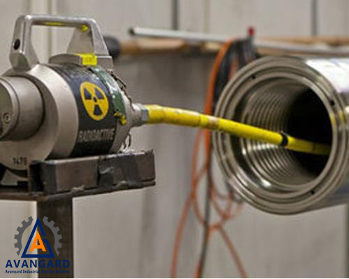
Radiographic Testing (RT) is one of the most widely used non-destructive testing (NDT) methods for detecting internal defects such as gas porosity. Planar defects can also be detected with proper orientation using radiography. This method is also used to identify changes in material composition, measure thickness, and locate extra or defective parts inside devices that are hidden from view. The primary advantage of using ionizing radiation in NDT is the fact that it can be applied to objects of various shapes and sizes, including microscopic electronic components. In RT testing, X-rays or gamma rays are used for radiography. The X-ray or gamma ray is directed at the object, and due to its low wavelength, the radiation is absorbed by the test piece. Industrial Radiographic Testing (RT) is one of the non-destructive testing (NDT) methods used to inspect cast components, revealing the presence and shape of macroscopic defects or other discontinuities inside the part. This method utilizes the penetrating power of X-rays or gamma rays through objects. The shorter the wavelength, the greater the penetration power of the radiation. Not all radiation penetrates the part; some of it is absorbed. The amount of absorption is a function of the density and thickness of the part. For example, if there is a cavity in the part, the emitted radiation passes through less metal compared to a sound part. As a result, the amount of radiation absorbed in the defective area will change. These changes in radiation absorption are recorded on a radiation-sensitive film, and the presence of defects is revealed. Since the type and size of defects have different effects on the performance of cast components, the inspector is responsible for interpreting the radiographic film to identify the type and size of defects such as gas porosity, subsurface cavities, sand inclusions, shrinkage cavities, dendritic shrinkage, cracks, inclusions, and more. In this regard, ASTM E155 has been provided to assist inspectors in better evaluating the defects found in manufactured parts.
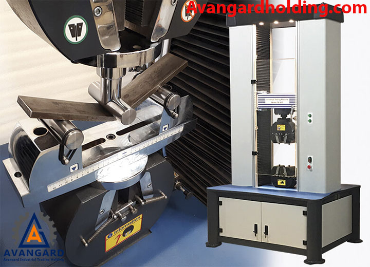
Mechanical properties testing, similar to non-destructive testing but with the difference that most of these tests are destructive, is one of the methods to ensure the performance and safety of a component. Mechanical properties testing is a fundamental part of the product design and manufacturing process, accompanying us from the desired material properties to the finalization of the part during manufacturing. Mechanical properties are described when a force is applied to a material. These properties are usually related to the elastic and plastic behavior of the material, and often, measuring these properties requires the destruction of the material. Therefore, mechanical tests are mostly destructive. However, at Avangard Engineering Company, with customer approval, a Y-Block is sometimes attached to the part, and after heat treatment cycles, the Y-Block undergoes the required mechanical tests to avoid damaging the part. At Avangard, depending on the alloy and the requirements of the part, various mechanical tests are performed, including:
1- Tensile Testing,
2- Compression Testing,
3- Hardness Testing,
4- Torsion Testing,
5- Bending Testing,
6- Impact Testing,
7- Fatigue Testing,
8- Creep Testing, and more.
The quality control unit of Avangard Company emphasizes continuous improvement in all stages, including initial design, casting, heat treatment, machining, and precise control of all procurement, production, and final inspection processes. This ensures that all expectations and requirements of valued customers and clients are met.

Our primary responsibility is to ensure that the quality management system is consistently maintained and operational, and that the delivered products meet the highest standards of our esteemed customers.
