فارسی
فارسی  Arabic
  Russian

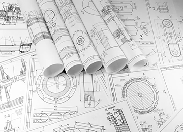
The construction and design of casting models, or in other words, casting modeling, as well as the making of casting molds, are considered one of the most important and widely used methods for producing and manufacturing metal parts. Casting is known in various fields around the world as a science, art, and technology. As much as the casting industry advances in terms of science and technology, it is still proven in practice that the quality of casting raw materials, the experience, taste, and art of the model maker and caster guarantee the production of a sound and defect-free part.
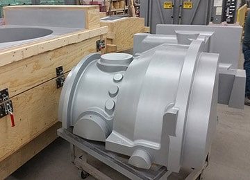
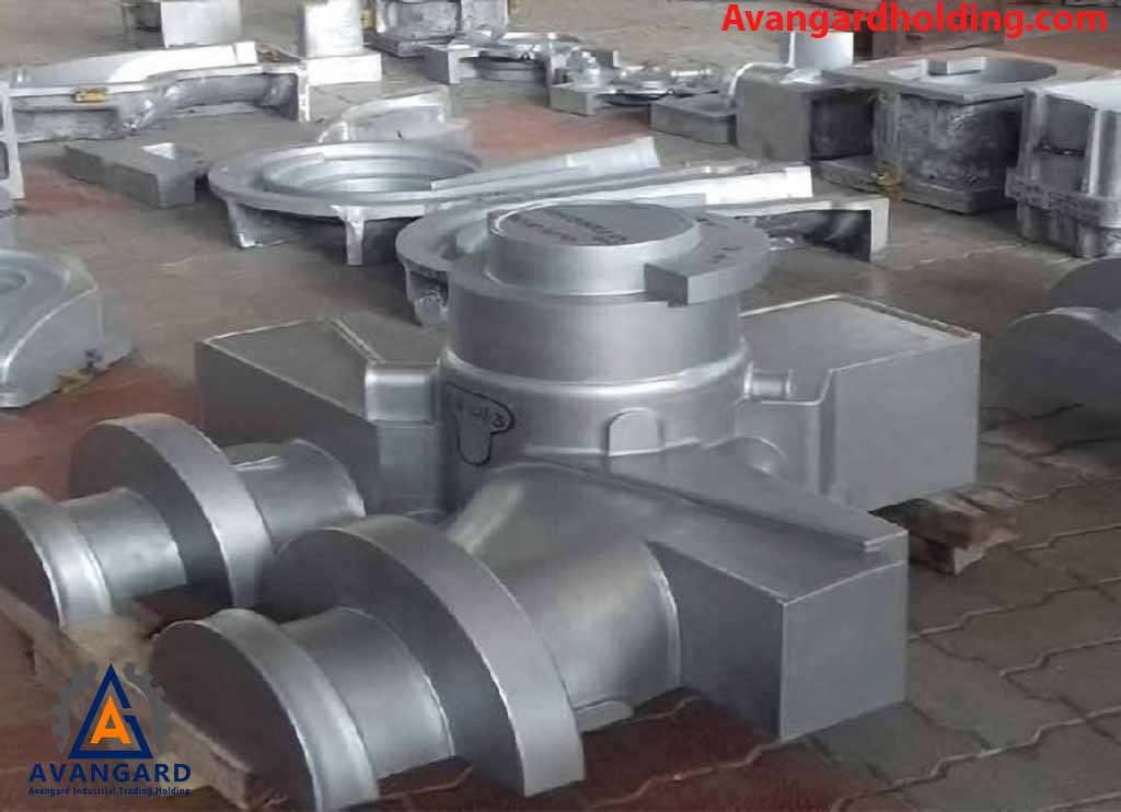
Design and modeling in the casting process, especially for the production of heavy parts such as crushing and road construction parts, is of great importance. These parts must be designed with high precision due to the harsh working conditions and the need for resistance to wear and impact. The use of 3D modeling software in this process allows for the examination of geometric details and simulation of the mechanical behavior of parts. Also, in the casting stage, the optimal design of gating and feeding systems is of special importance to reduce potential defects such as gas cavities and contractions, and to improve the final product quality.
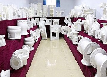
Before the casting process, modeling is required. Casting modeling is the design and construction of a casting model or pattern in the form of a one-piece or multi-piece part. Regarding casting modeling and making various types of models, such as plate models and loose models made of aluminum casting models, wooden casting models, polystyrene casting models or foam casting models, as well as performing all reverse engineering of industrial parts, casting design, drawing casting parts, and all production of parts by specialized casting of steel, cast iron and non-ferrous metals, Avangard Company, with more than two decades of experience, is ready to provide casting modeling services with excellent quality and reasonable prices, and you can contact our experts now to inquire about prices and place an order.

The design and modeling of casting is of great importance because it plays an important role in the industry of manufacturing and designing metal parts. Now, considering that the design of a casting model is one of the important parts of production processes by casting, we will discuss the design and construction of various types of casting models below.
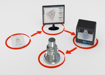
Avangard Company, with its experienced and professional staff and appropriate tools for modeling, has the ability to design, construct, and produce any kind of model and complex parts. In the first stage when employers contact Avangard Modeling to carry out a casting modeling project, there are usually three situations:
- In the first method, the contractor delivers a 3D file of the mold that needs to be made by our team.
- In the second method, the contractor has a two-dimensional drawing of the part and the 3D file is not available.
- In the third method, the contractor delivers the part itself to our company and requests the construction of its casting model, which we will discuss further in the reverse engineering section below.
In all three cases, the technical engineering team of Avangard examines the project topic and the quantitative and qualitative generalities and provides a cost estimate and a time estimate for the construction of the casting model to the employer. The time provided for the projects is different based on the complexity of the models. At this stage, a contract is concluded between the employer and Avangard Company to carry out the project, and the design and construction of the casting model and mold begins by the technical team. Avangard Company, with its experienced team, will certainly deliver the highest quality and most accurate model to you in the fastest possible time. We will examine the issues in great detail in the text below.
Casting model (Pattern) design is widely used due to the importance and extensive application of various casting methods in production processes. Approximately fifty percent of the parts in various industrial machines are produced by casting, such as parts with complex shapes or metals with low plasticity. Considering that a significant portion of industrial products is related to cast parts and that the casting industry has played a crucial role in the development of technology and production in various industrial cities, the drafting and manufacturing of casting models must be carried out in a manner that is compatible with the conditions and capabilities of molding. Consequently, given the importance of comprehensive design and modeling (Pattern Making), Avangard Casting Modeling Services Company fully examines all processes before and after the design of a casting model to ensure the production of high-quality and flawless parts.
As mentioned in the book Casting Modeling, a casting pattern is an object made from various materials and is used to create the mold for the desired part in casting. Each type of pattern has a specific role in the casting mold-making process. Without the design of patterns and casting molds, shaping cast parts would be impossible. Therefore, it can be stated that modeling holds significant importance in the production of various cast parts and is a crucial tool for mold-making and casting. Casting patterns are categorized in different ways based on their specific characteristics, which will be discussed further. Additionally, it is worth noting that the design of casting patterns at Avangard Company is carried out by experienced engineers.
-
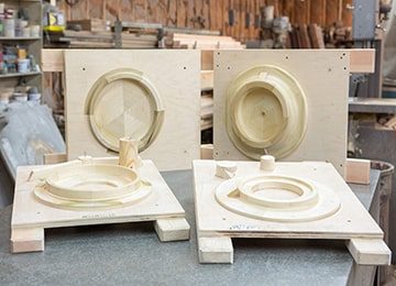
Wooden Casting Patterns
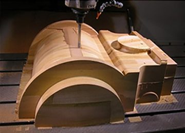
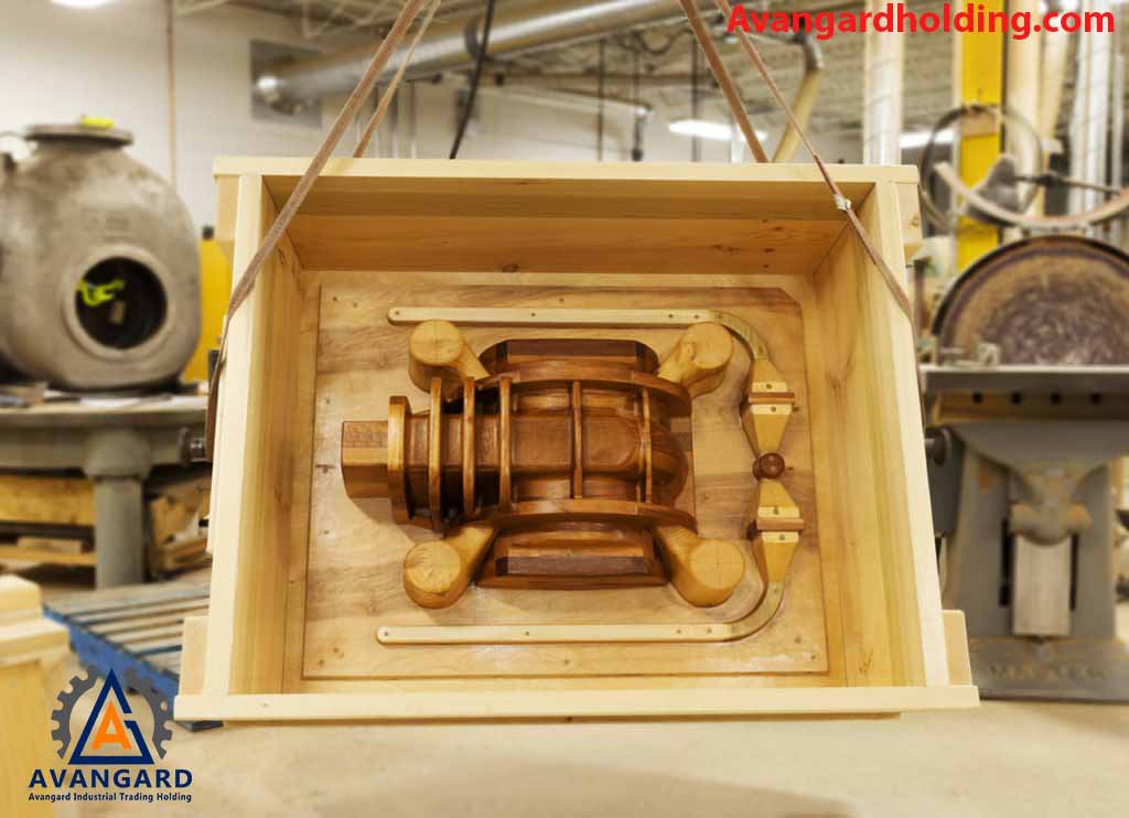
Wooden casting patterns are one of the oldest and most widely used materials in the casting modeling industry, and they are also among the most cost-effective. These patterns are commonly used in specialized casting modeling workshops. Wooden patterns are suitable for low-volume molding and are typically made from woods such as pine, cypress, alder, maple, and walnut.
Below, we provide explanations regarding the physical and mechanical properties and applications of some woods used in modeling:
Understanding the mechanical properties of woods helps us avoid mistakes when selecting the right type of wood for various industries, including modeling. Some of these mechanical properties include:
Splitting capability, bending ability, excellent elasticity, tensile strength, compressive strength, torsional strength, bending strength, and the effect of moisture on wood.
*The most important properties and applications of some woods are briefly outlined below.
– Alder Wood: It is soft and lightweight, with a yellow color, high splitting capability, and low elasticity. It is suitable for making small and medium-sized patterns and mold-making.
– Maple Wood: It is hard with smooth fibers and a white color. A unique feature of this wood in the modeling industry is that it dries quickly after being cut and is highly durable. This wood is used for making delicate and small patterns, furniture, musical instruments, veneering, etc.
– Walnut Wood: It is hard and sturdy, with excellent physical and mechanical quality. It is very workable, durable, and resistant, with excellent sawing, planing, polishing, finishing, and varnishing capabilities. It has high vibration resistance, excellent adhesive properties, good wear resistance, and exceptional resistance to fiber separation in water and moisture. Its excellent nail and screw holding capabilities make it ideal for home decor, furniture, gunstocks, and small, precise casting patterns.
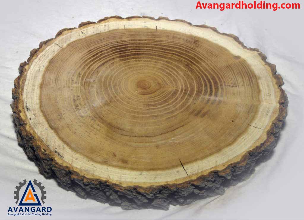
– Black Wild Cherry Wood: It is heavy, hard, and sturdy, making it excellent for crafting walking sticks, precise modeling, and more.
– Linden Wood: Linden wood, also known as basswood, is soft and lightweight, with a gray color and good bending capability. It dries well and is used for drafting tables, wood carving, modeling, and more.
– Changes in the moisture content of wood can cause alterations in its shape and volume, a phenomenon referred to as wood movement. Modelers must pay close attention to these factors; otherwise, warping or twisting of the model is inevitable.
– Generally, efforts are made to construct all models using hard, durable, and sturdy woods. For larger models, more suitable woods are selected, such as redwood, oak, whitewood, and others.
– For creating small, high-quality models at reasonable prices, and considering their delicacy, woods such as maple, ash, walnut, birch, and others are used.
Avangard Holding, with over two decades of experience, delivers high-quality models at reasonable prices and in the shortest possible time to esteemed foundries.
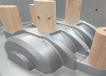
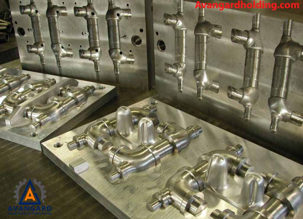
2. Metal Casting Patterns
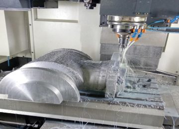
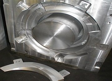
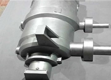
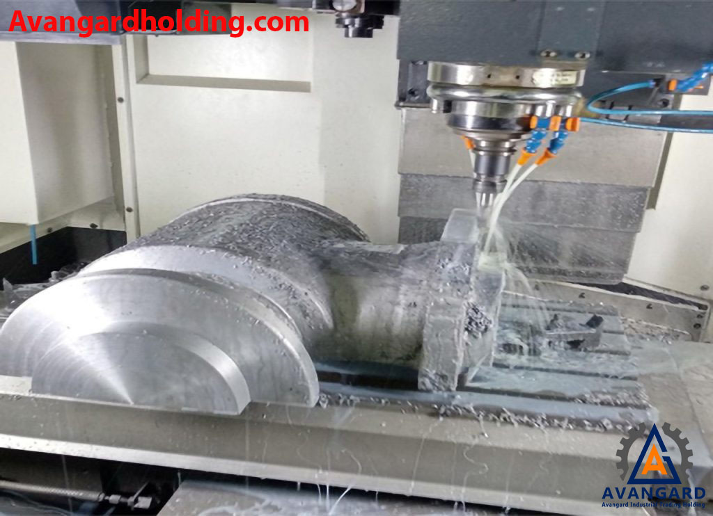
Metal casting patterns are models that are sometimes made directly from raw materials (ingots) using machines such as lathes, milling machines, CNC machines, etc. However, they are usually produced through casting, and wooden or foam master patterns are used for their casting. Metal patterns are considered permanent patterns because they retain their quality and dimensions even after repeated use in molding. Typically, metal patterns are designed and manufactured for casting runs exceeding 20 pieces. Common materials for metal patterns include aluminum, steel, cast iron, and others. When creating master patterns (primary patterns) for casting secondary (metal) patterns, secondary shrinkage is also taken into account. For example, a shrinkage allowance of 1% is usually applied when converting a wooden pattern to aluminum, as the metal pattern requires one casting process. If machining is needed, additional machining allowance or surface finishing is also considered.
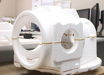
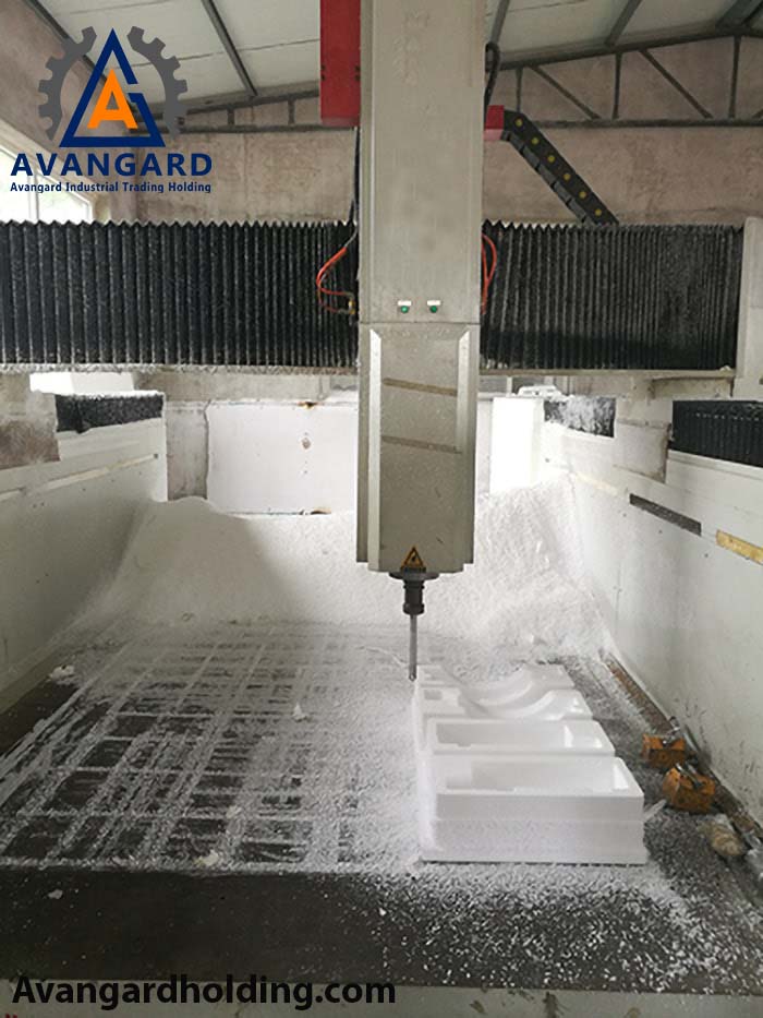
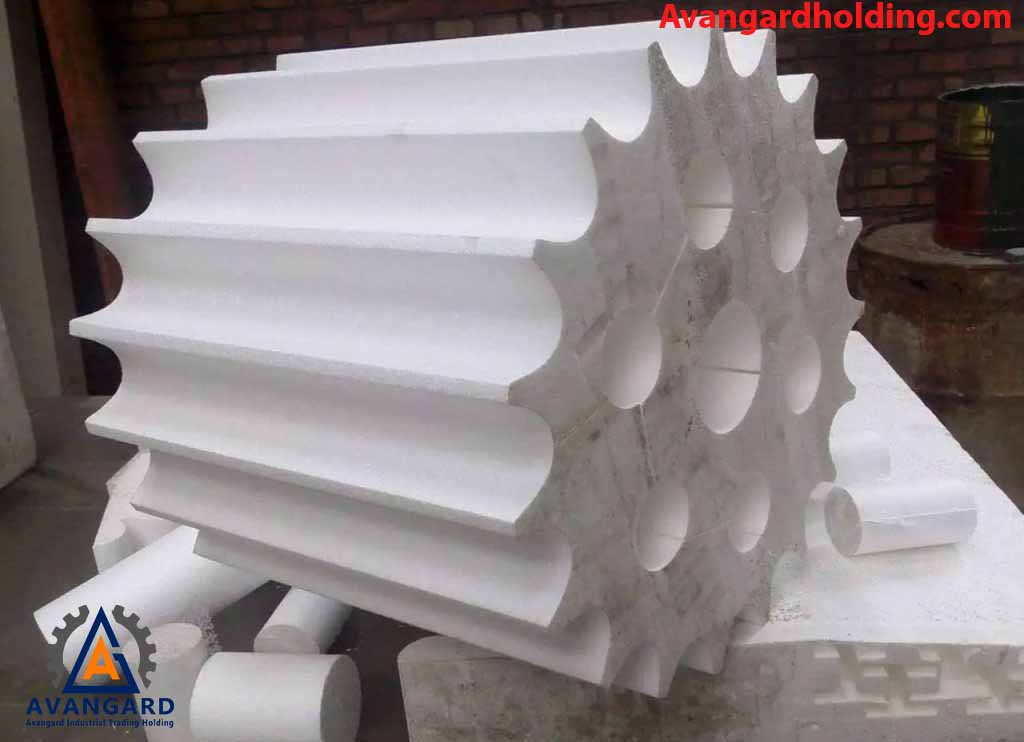
3. Disposable Patterns (Foam – Polystyrene) for Casting
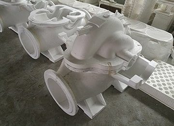
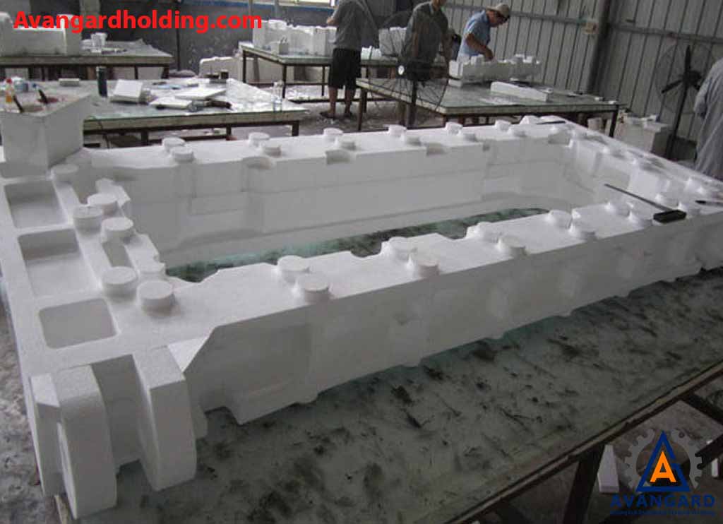
Foam casting patterns: Polystyrene is used for expendable patterns. In the expendable pattern method, if we have a part that is heavy or if we only need one unit of that part, and if making wooden or metal patterns is not cost-effective, we use foam patterns. In this method, the pattern is not removed from the sand mold. Instead, when the molten metal reaches the mold, the pattern melts away, and the molten metal takes its place within the mold cavity.
In this method, there is no need to construct a core box. After creating the pattern, it is coated with a special material suitable for the molten metal, whether it is cast iron, steel, or non-ferrous metals. Then, the molding and casting process begins. To produce cast parts, we need to create a pattern. The part produced from the foam pattern, after applying modeling shrinkage or contraction coefficients, will precisely match the desired part in terms of dimensions and shape.
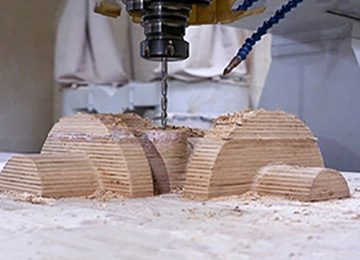
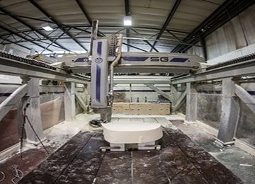
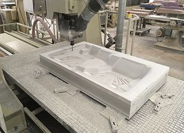
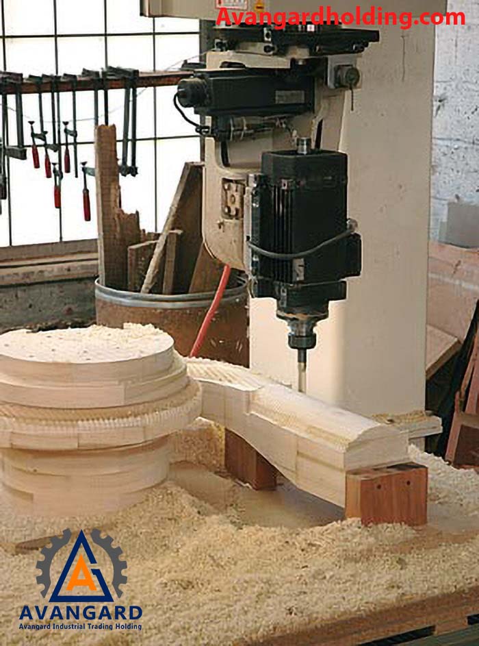
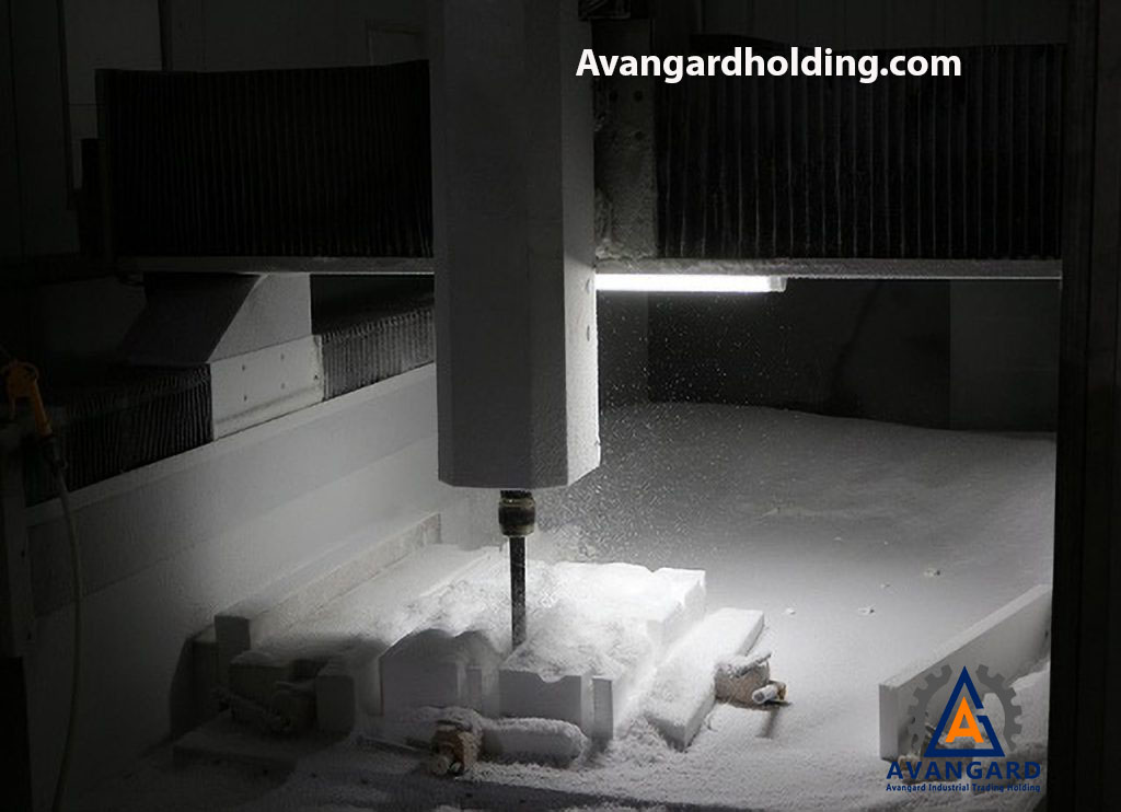
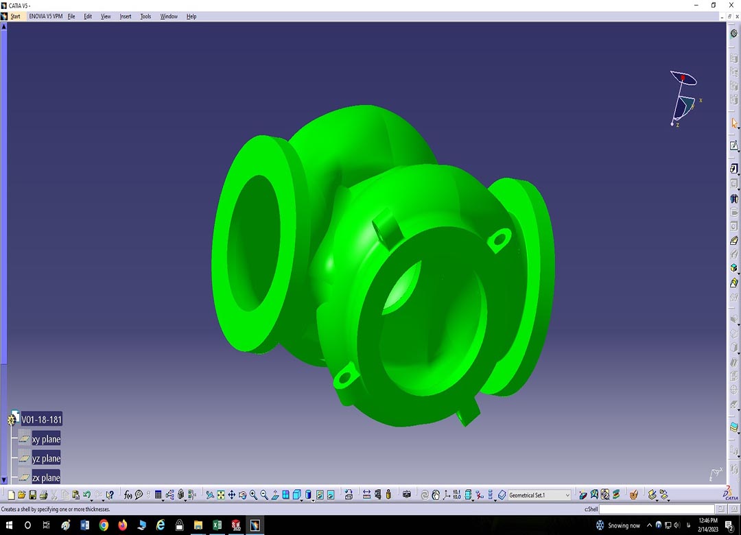
Avangard Company, with over two decades of experience in pattern making and casting production, relies on metallurgical expertise from top universities both domestically and internationally. Using specialized software such as CATIA, SolidWorks, and other professional tools, the company designs foam patterns. With multi-axis CNC machines, all patterns are produced in three dimensions, tailored to your required sizes and dimensions, with the highest precision and most competitive prices.
Some Advantages of Using Foam Patterns in Casting:
- Very low cost of producing foam casting patterns compared to other types of patterns.
- Ability to produce parts with negative drafts without the need for applying pattern draft angles.
- Very high precision due to manufacturing with CNC machines.
- Extremely fast production of foam patterns.
In conclusion, this type of pattern is highly suitable for casting parts of all sizes, especially very complex, large, and heavy parts, and offers significant economic efficiency.
4. Composite Casting Patterns
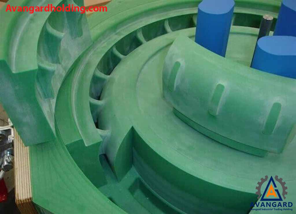
Composite casting patterns refer to patterns made by combining two or more materials, such as wood, plastic, epoxy resin (Araldite), silicone, and others.
- One-Piece Casting Molds
- Two-Piece Casting Molds
- Multi-Piece Casting Molds
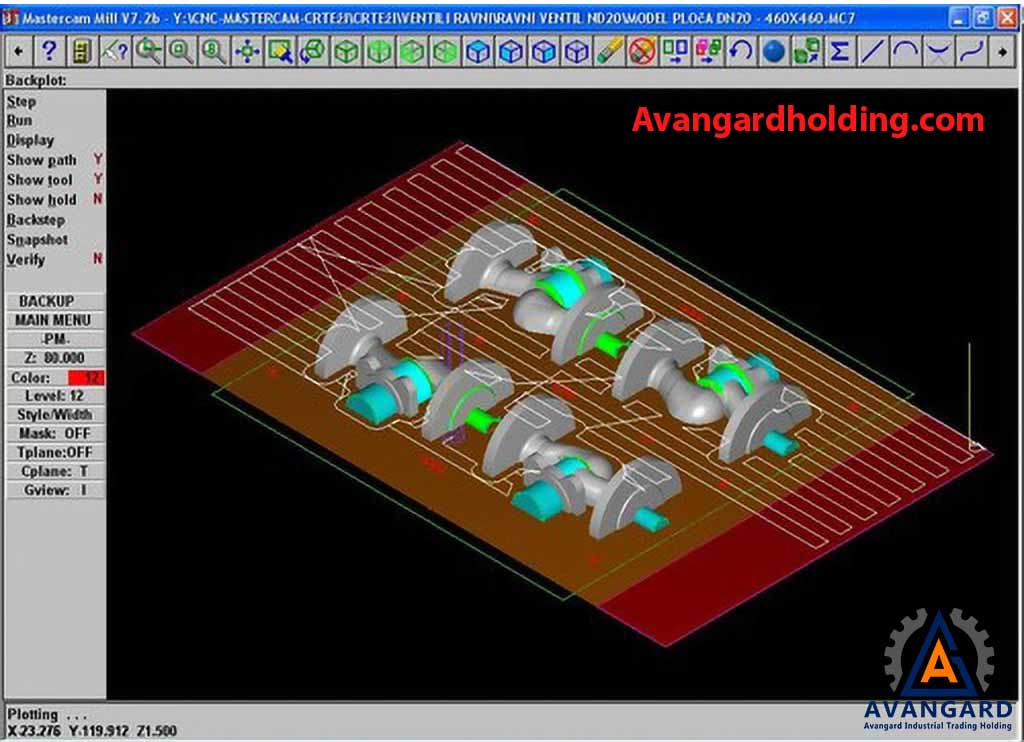
Machine Casting Patterns
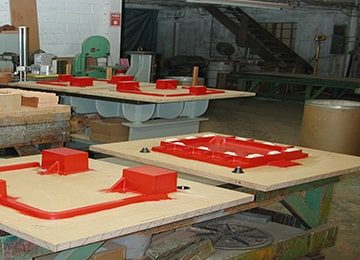
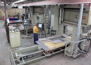
If you need to produce a large number of cast parts, it is better to use machine patterns. In this method, machine casting patterns are mounted on a special molding machine plate, usually made of metal, and are commonly referred to as machine plate patterns in the casting industry. These patterns are molded using semi-automatic or fully automatic machines. They are used in mass production, and it is worth noting that all services related to the production of plate patterns in casting are carried out at Avangard Company with high quality and speed.
Hand Casting Patterns
Hand casting patterns are models for which machine molding is either not feasible or cost-effective. These patterns are manually molded in flasks or sand boxes. Avangard Company provides various sand casting pattern-making services with high precision and affordable prices.
The structure of these patterns is designed for manual (traditional) molding and casting. Typically, these parts have irregular (broken) parting surfaces and are slower to produce compared to machine patterns.
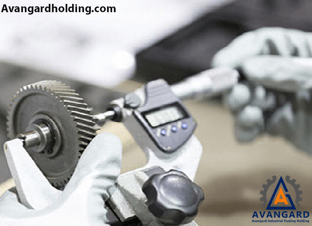
The precision of casting patterns significantly impacts the quality of the mold and the final part. As mentioned, if the design and construction of casting patterns lack proper quality and accuracy, it will ultimately result in parts with very low surface quality. Therefore, before examining pattern-making in the casting process, it is essential to familiarize ourselves with various manufacturing methods for industrial parts and molds. Finally, we should evaluate molding, casting, and the design and construction of casting patterns.

Metal Casting Patterns
Metal casting patterns, also known as permanent patterns, are reusable even after multiple molding and casting cycles. These patterns are ideal for long-term molding processes and are made from metal alloys such as aluminum, cast iron, steel, and others. The cost of producing these patterns is relatively higher compared to other types of patterns.
Wooden Casting Patterns
Wooden casting patterns are models entirely made of wood, and most master patterns (primary patterns) are of this type. These patterns are considered temporary because, after several molding cycles, they may deform or change dimensions due to factors such as environmental humidity, mold moisture, and other climatic conditions. If the number of casting cycles is below 20 to 30, this type of pattern is used. For medium to low-volume orders, wooden patterns are recommended due to their significantly lower production cost compared to metal patterns.
Foam Casting Patterns
Foam casting patterns are disposable models that are destroyed after the molding process. When we have a part that is heavy or when only one unit of the part is needed, and making wooden or metal patterns is not cost-effective, we use foam casting pattern technology.
| Property | Cast Iron | Aluminum | Wood | Foam |
| Machinability | Excellent | Excellent | Excellent | Good |
| Wear Resistance | Excellent | Good | Weak | Weak |
| Strength | Excellent | Good | Weak | Weak |
| Repairability | Weak | Moderate | Good | Weak |
| Corrosion Resistance | Excellent | Excellent | Excellent | Weak |
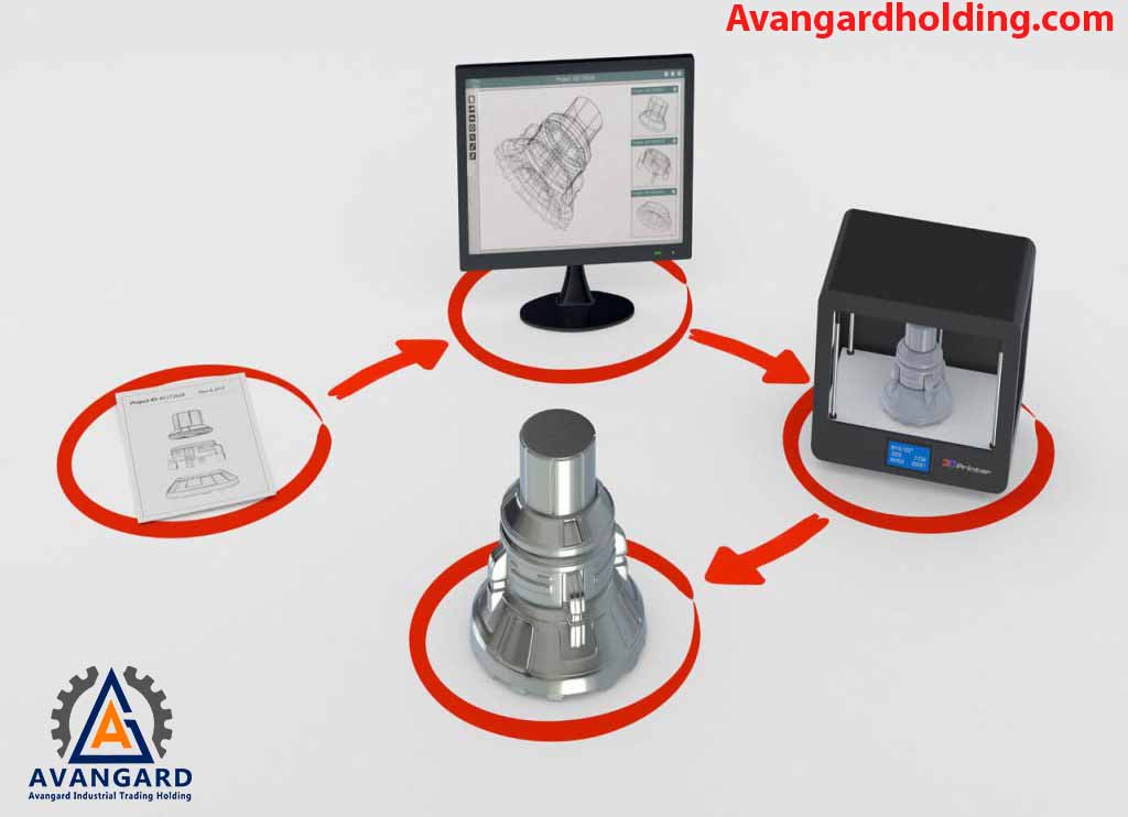
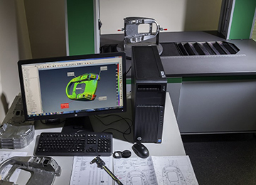
Today, using advanced equipment and precision tools, after obtaining the necessary drawings and information about the desired part, the model is designed and constructed using 3D printers or CNC machines. Below, we will briefly explain the methods and tools for drafting parts.
At this stage, after designing the scanned part, to compensate for any dimensional and structural changes that occur during the casting or modeling process, additional factors such as shrinkage, draft, machining allowance (overcut), and more are added to the design using advanced software, and the casting model is prepared.
Casting Shrinkage Consideration (Contraction Allowance / Shrinkage Allowance)
One type of casting shrinkage is volumetric shrinkage of steel during solidification. A metallurgical engineer must calculate the shrinkage of the part during solidification based on the material and compensate for it through proper feeding to ensure complete filling of the part’s core and prevent defects caused by shrinkage during solidification. Alloying elements such as tungsten and nickel have a negative effect, while elements like manganese, chromium, silicon, and aluminum have a positive effect on shrinkage. Another type is linear shrinkage, which the modeler must consider based on the material. For example, for aluminum and cast iron, it is about 1%, for plain carbon steels about 2%, for stainless steels about 2.6%, and for Hadfield steels (manganese steels) about 2.8%. From the moment the pouring into the sand mold or die-casting mold occurs, and as the part begins to solidify until it completely solidifies and reaches ambient temperature, it experiences linear shrinkage. The person responsible for casting modeling must account for shrinkage or contraction after solidification and make the model slightly larger. Typically, this shrinkage ranges between 0.5% to 3%. In fact, the amount of shrinkage varies depending on the system and molding method. It can also differ among foundries based on the type of binder, sand, compaction, and ramming. In this regard, Avangard Modeling applies this shrinkage correctly based on experience from over 10,000 cast parts in various industries and precise engineering calculations of linear shrinkage.
Draft Allowance Consideration
To prevent friction on surfaces perpendicular to the parting line, all these surfaces are designed and constructed with a draft angle to allow easy removal of the model from the mold. The calculation and application of draft are done in the following three ways: 1. Positive draft allowance 2. Negative draft allowance 3. Neutral draft allowance In the positive draft method, the draft amount is added to the model size, slightly increasing the part’s weight. The Avangard modeling group applies the appropriate draft during design based on the part’s application and the three types mentioned above.
Machining Allowance Consideration
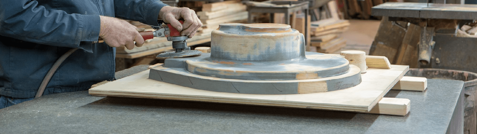
The surface obtained in sand castings generally has low surface quality, and in many cases, these parts undergo specialized machining or grinding processes to improve surface quality. During various machining stages, some metal is removed from the part. To compensate for this, a machining allowance is added to the model during casting. The amount of machining allowance depends on the alloy type, part size, production volume, molding method, and other important factors. Sometimes, additional tabs or projections are added for clamping during machining, which are removed after machining. The amount of machining allowance varies depending on the casting quality and the part’s sensitivity to operations such as turning, grinding, drilling, etc. Typically, the minimum machining allowance for surfaces requiring machining is 3 mm or more. Since increasing thickness raises the part’s cost, alternative production methods such as die-casting (pressure casting) and precision casting can be used to minimize machining requirements.
Shake Allowance Consideration
Typically, when removing the model from the mold cavity, the molder taps or shakes the model to facilitate its removal. This causes the final cavity in the mold to become slightly larger. To compensate for this during the molding process, the model dimensions must be reduced. Since there is no specific standard value for this allowance, as it heavily depends on the molder’s skill, a negative allowance is often observed. One method to reduce this negative allowance is to apply an additional draft to the model. Tapping the model enlarges the mold cavity, resulting in a larger cast part.
Distortion Allowance Consideration
During mold cooling, stresses caused by different cooling rates in various parts of the component may lead to distortion. This is more noticeable in molds with a high length-to-width ratio. This issue can be minimized by applying an initial deviation to the model in the opposite direction.
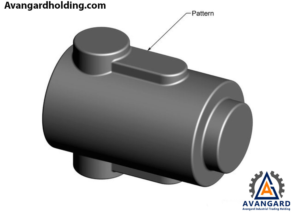
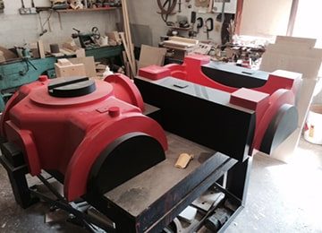
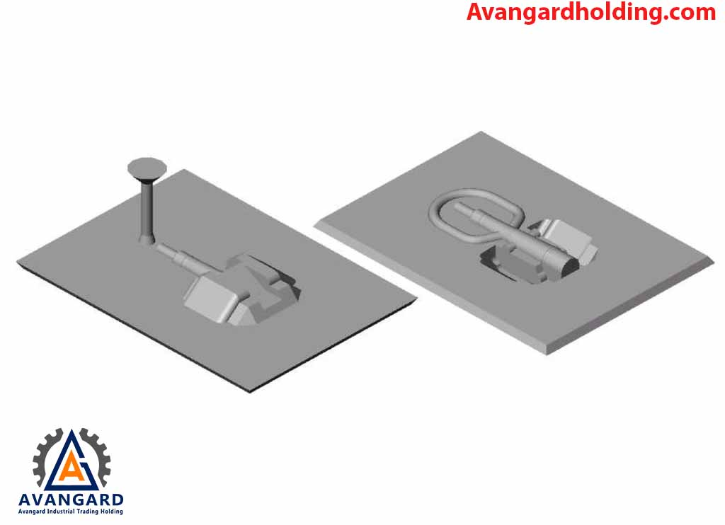
Based on the appearance of the part, its complexity, design type, and production technology, the designer determines a parting line for the part. Typically, the part is divided into two sections, and then the model is constructed accordingly.
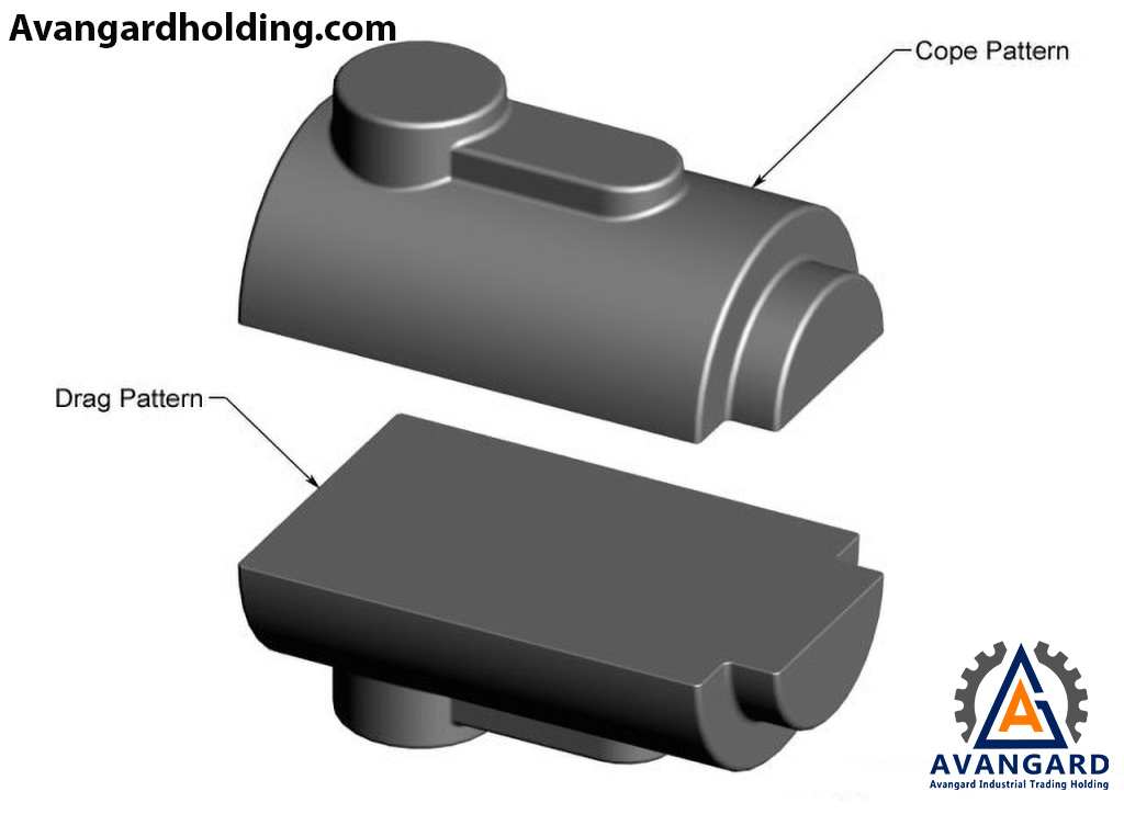
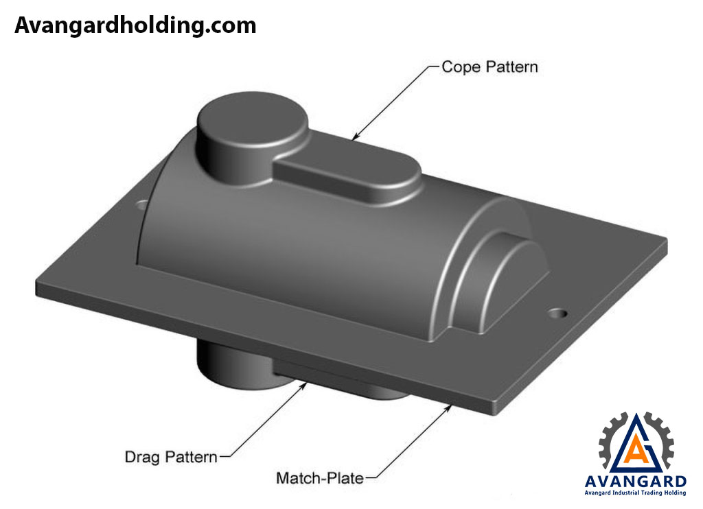
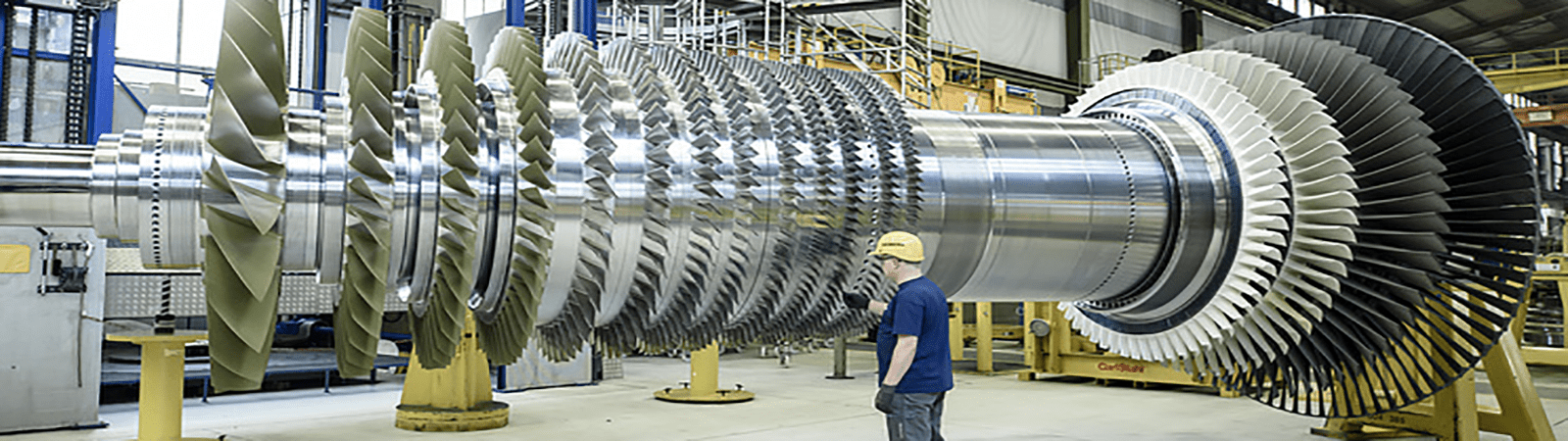
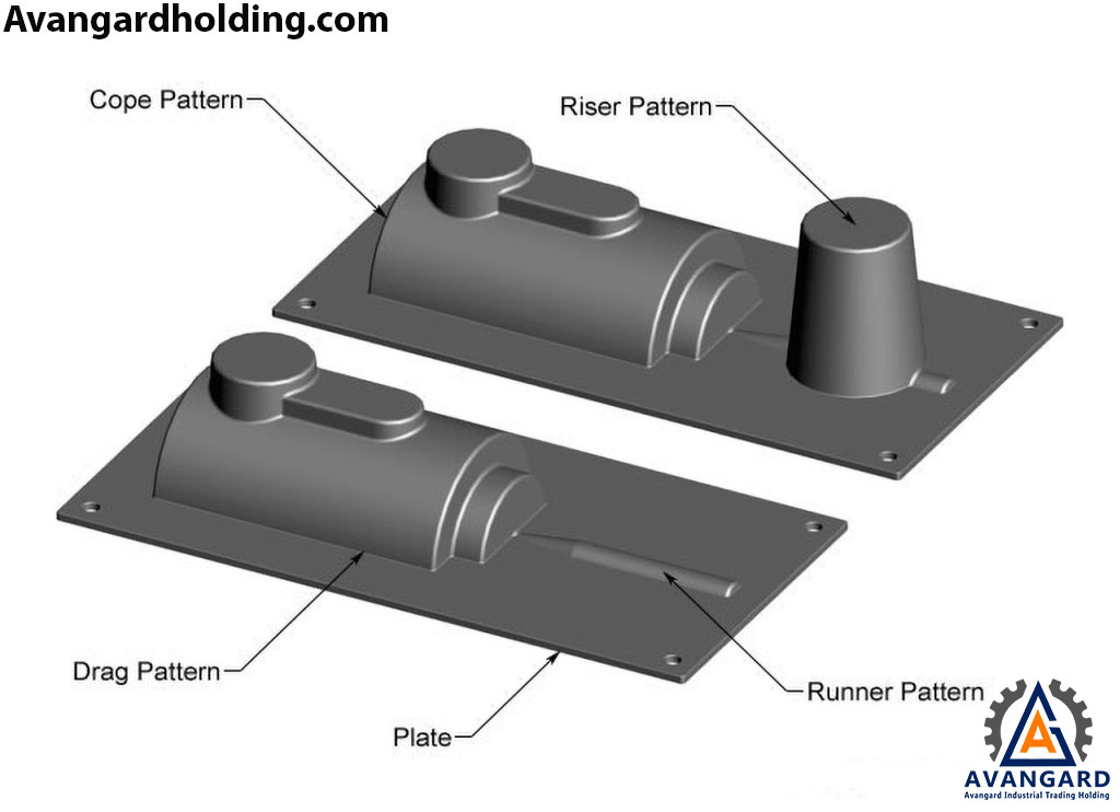
In the final stage, the gating system is installed, and the model is mounted on separate plates known as the bottom plate (tie-under) and the top plate (tie-over). Another type is the match plate pattern, which consists of upper and lower parts called cope and drag portions. These models are mounted on both sides of a single plate, allowing for quick removal from the molding material. Another method in casting modeling is the construction of one-sided match plates. These models, also known as cope and drag patterns, are well-known in the large-scale casting industry. One-sided match plates are primarily used for large-sized casting models. In this type of model, both sides of the model are mounted on separate plates. In fact, these models can be hooked to vertical or horizontal machines and formed into molds using molding materials. Avangard Holding, with over two decades of experience and advanced academic qualifications from prestigious universities both domestically and internationally, as well as the design and technology of over ten thousand parts for industries such as machinery manufacturing, automotive, mold making, oil and gas, petrochemicals, power plants, cement, and mineral processing, assures you, esteemed industrialists, of delivering services with the highest quality and most competitive prices.
To view and explore casting products, click on the link.
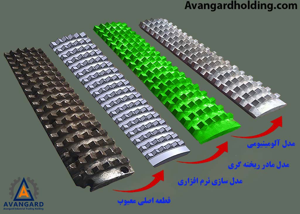
Reverse engineering in casting parts (Reverse Engineering) is a modern method through which, by disassembling the components of a product or object and reassembling them, we obtain important and precise data about the product’s design. Reverse engineering is an accurate method to achieve current technology and existing products.
In this process, experts from various fields of basic and applied sciences, such as mechatronics, metallurgy, polymer chemistry, mechanics, physics and optics, electronics, etc., form highly specialized groups to fully understand the implementation method of a product with advanced technology. Using advanced equipment, precise laboratory devices, and proper organization of research and development (R&D) structures, they strive to obtain details, documents, and design drawings of the desired product. After prototyping and semi-industrial production (Pilot plant), if feasible, the production of the aforementioned product is carried out in accordance with the technical standards of the original product.
It is worth noting that the use of reverse engineering is a very suitable and precise method for developing countries, or so-called third-world countries, to access the details of technology, progress, and development of a product. These countries, which are often weak in terms of technology, alongside other methods and policies for obtaining technical and scientific information, consider reverse engineering the best method to access technology. They try to use reverse engineering to recover technical knowledge, functional mechanisms, and other important information about existing parts. Alongside using forward engineering methods (Forward Engineering) and modern manufacturing techniques, as well as various testing and laboratory facilities such as molds, test gauges, precise engineering fixtures, and precision control devices, they establish highly equipped and advanced production companies to manufacture the aforementioned products. It is also noteworthy that reverse engineering can be used to address defects and enhance the features of existing products. For example, in the United States, reverse engineering has been used by the powerful company “Ford Motor” on products of the giant company “General Motors,” and vice versa, to maintain competitive conditions and address product defects.
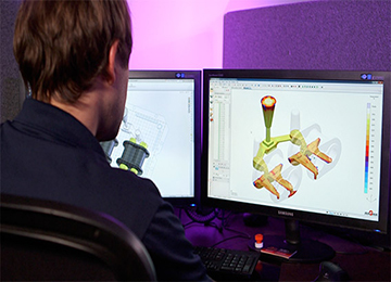
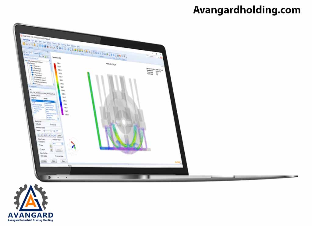
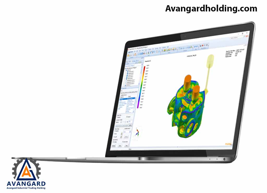
At Avangard Holding, for modeling and casting services using reverse engineering, we proceed as follows: When a part is brought to the company for casting, it undergoes the following steps based on the available documentation. First, the coordinates of the part are obtained through scanning, and then a 2D drawing and a 3D model are prepared based on the point cloud. The casting model drawing is prepared based on the part’s drawing and model, considering the explanations and considerations mentioned earlier. Depending on the importance of the cast part, the casting simulation process is performed using numerical methods to calculate the quality of cast parts, considering mold filling, cooling, and solidification, as well as predicting mechanical properties, thermal stresses, and distortion. Pre-production simulation accurately analyzes and describes the quality of the part. The benefits of simulation go beyond reducing initial prototyping before production, as the precise design of the casting system leads to energy, material, and tool savings. Analyzing and simulating the casting process using various software offers advantages such as: • Continuous improvement of productivity • Increased accuracy • Reduction in scrap material volume • Cost reduction The casting simulation process is carried out using software such as ProCAST, SUT CAST, etc. ProCAST software is one of the powerful computer-aided engineering (CAE) tools in the market for finite element analysis (FEA). This software, a product of ESI Group France, uses the finite element method to model casting processes. Its capabilities include flow analysis, thermal analysis, and stress analysis of cast parts, minimizing defects caused by pouring (such as gas entrapment or turbulence) and solidification (such as porosity or gas). SUT CAST software is also one of the most powerful tools for visualizing, modeling, analyzing, and optimizing the casting process. This software simulates molten metal from common casting alloys in sand or permanent molds. SUT CAST also simulates mechanical properties (hardness, tensile strength, and yield strength) and the microstructure of castings.
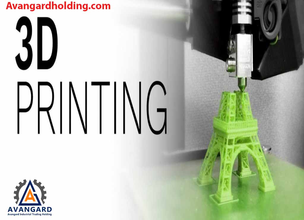
For low-volume production, the initial prototype of the model is prepared using rapid prototyping methods, such as 3D printing or CNC-made foam models. For mass production, models are created through aluminum or cast iron casting and high-precision machining to ensure quality and accuracy.
انتخاب مواد و آلیاژ بر اساس آنالیز مشتری یا تهیه نمونه از قطعه فابریک و آنالیز توسط دستگاه کوانتومتر و تعیین ساختار میکروسکوپی و همچنین مشخص نمودن خواص مکانیکی قطعه و یا انتخاب مواد به کمک نرم افزار CES صورت می گیرد و فرایند مدل سازی و تشخیص روش مناسب ریخته گری متناسب با آن انجام می گردد. پس از ریخته گری بررسی ابعادی، آنالیز مواد و کنترل کیفیت قطعه تولیدی صورت می پذیرد، و در صورت تایید بودن در ادامه مراحل برشکاری راهگاه و تغذیه و سرانجام عملیات شات بلاست، سند بلاست و … همراه شن زنی بر روی قطعات صورت می گیرد. قطعاتی که بر اساس عملکرد یا نیاز مشتری و یا مطابق با تعیین ساختار و خواص مکانیکی قطعه فابریک به عملیات حرارتی نیاز دارند تحت عملیات حرارتی یا تنش گیری به شرح ذیل در کوره قرار می گیرند. • تنش گیری(stress relieving) • سخت کاری و تمپر (Quench & Temper) • نرماله (Normalizing) • آنیل (Annealing) • آنیل انحلالی و پیرسازی(Solution & aging)
سرانجام توسط تیم کنترل کیفیت شرکت آوانگارد، آزمون های مخرب (DT) نظیر تست کشش، تست فشار، تست سختی سنجی، تست ضربه و… یا آزمون های غیر مخرب (NDT) از قبیل بازرسی چشمی(VT)، بازرسی مایع نافذ (PT)، بازرسی ذرات مغناطیسی(MT)، بازرسی رادیوگرافی(RT)، بازرسی التراسونیک(UT)و …بر اساس در خواست و استانداردهای الزامی یا اختیاری مشتری اجرا می گردد و پس از تایید توسط تیم کیفی آوانگارد برای بسته بندی و ارسال به مشتری اقدام می شود.
Join us as we explore some of the applications of reverse engineering: 1. Recreating custom antique objects Reverse engineering is one of the reliable methods for creating a product when no information about it is available, or only the product or part itself is in hand. For example, imagine the original shape of a product or part. When a design is created using engineering software, ensuring that the computer-generated model matches the physical sculpture is challenging. However, it makes recreating the product hassle-free, as the physical model of the desired product serves as the primary source of information for designing the product using software and computers. 2. Completing and improving parts A part or equipment may require specific updates and upgrades. If a replacement for the desired part cannot be found, you can use reverse engineering to create a version of the original design. Not only can you analyze parts for defects, but you can also redesign parts to change dimensions, thickness, or use more resistant materials with different properties. 3. Creating CAD models In modern reverse engineering, files designed by skilled engineers can be archived and studied as references for the future. This method also allows you to test production stages and find ways to increase productivity using computer-designed models. This helps engineers obtain accurate information and save time. 4. Identifying vulnerable dimensions of a product or part Reverse engineering continues to assist in finding defects and errors in products. When analyzing an existing product using reverse engineering technology, you can identify defective parts. Paying attention to the digital files extracted through this scientific and empirical process clearly reveals existing flaws and shortcomings, allowing you to plan for repairs or replacements.
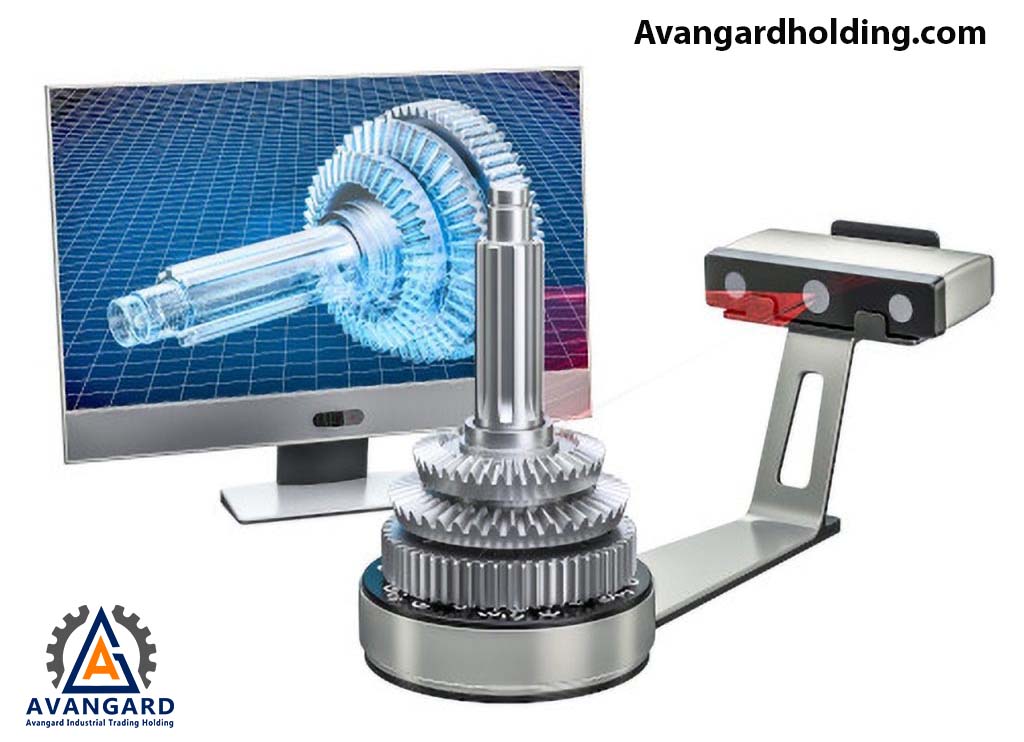
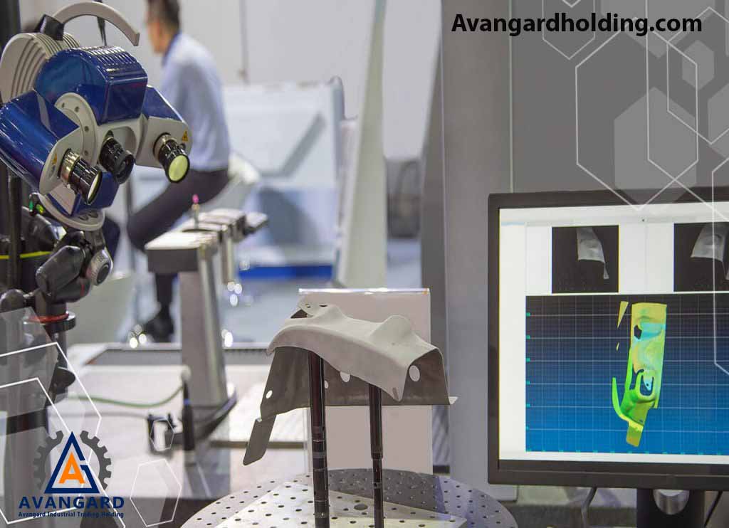
A 3D scanner is a powerful tool that allows for obtaining precise information about the external shape and appearance of a part. This technology is one of the fastest, most accurate, and simplest ways to gather information about the form and shape of a part. The data extracted from 3D scanning is ultimately converted into a 3D model of the desired part. A 3D scanner is a powerful device that analyzes an object or entity in the real world and collects information about its characteristics and shape, such as color, dimensions, and appearance. The data obtained in this process is used to create a 3D model. In fact, it can be said that 3D scanners are powerful tools for producing a model similar to the real and original sample, with other common applications in the production of prosthetics, prototyping, industrial design, documentation, and other industrial uses. The result is a 3D file on a computer that can be saved and edited, and this file can represent an object, environment, or person. The design and engineering team at Avangard Company provides optical dimensioning services and, using the most advanced industrial digitizers and optical CMMs, offers 3D scanning and dimensioning services without limitations in material type, dimensions, or size to industrial entities. With 3D scanning, we can achieve greater accuracy, speed, and reliability for critical projects compared to other inspection methods.
Contact 3D Scanner
This type of scanner collects and extracts relevant information through physical contact and touching the desired part. In the contact-based scanning method, the part must be well-finished to achieve a specific level of smoothness and surface quality to be scannable. Contact 3D scanners use three different mechanisms for 3D scanning an object: This system consists of a relatively rigid arm that slides along a rail. This type of contact 3D scanner is suitable for scanning profiles with flat surfaces or surfaces with very simple convexities. A rigid arm composed of several segments and precise angular sensors, where the position of the scanner arm’s end is determined by calculating the angle of each joint. This type of 3D scanner is highly suitable for scanning internal parts of an object or hard-to-reach areas. A combination of the two aforementioned contact 3D scanners, where this type of contact 3D scanner consists of an articulated arm that slides and moves along a rail. This type of contact 3D scanner is commonly used for scanning large parts and objects with internal cavities and porous surfaces.
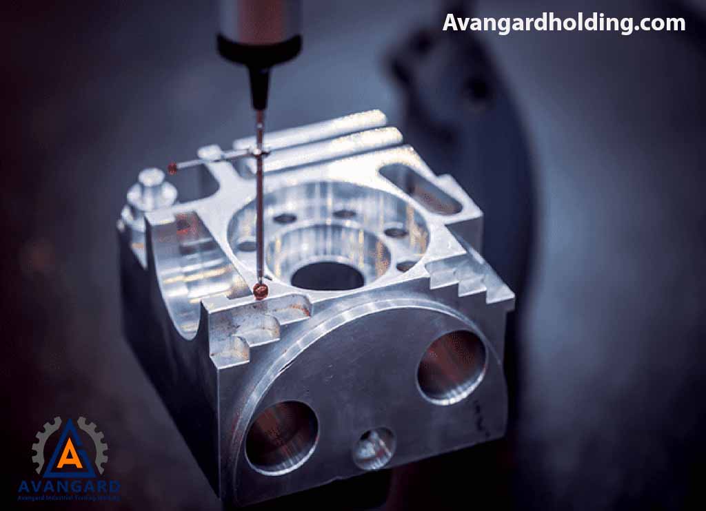
CMM
CMM, which stands for Coordinate Measuring Machine, is a type of contact 3D scanner often used in industry and can be very precise. One limitation of CMM 3D scanners is that they must be in contact with the object to scan it. Notably, the 3D scanning process with CMM equipment may alter or even damage the object. This subtle point can be very critical. Imagine trying to scan sensitive objects such as ancient artifacts with a contact 3D scanner! Another drawback of CMM is that it is slower compared to other 3D scanners. The physical movement of an arm with a probe attached to the end of the CMM 3D scanner can be very slow. The fastest CMM 3D scanners can only operate at 100 Hz. In contrast, optical 3D scanners, such as laser 3D scanners, can operate at 10 to 500 kHz.
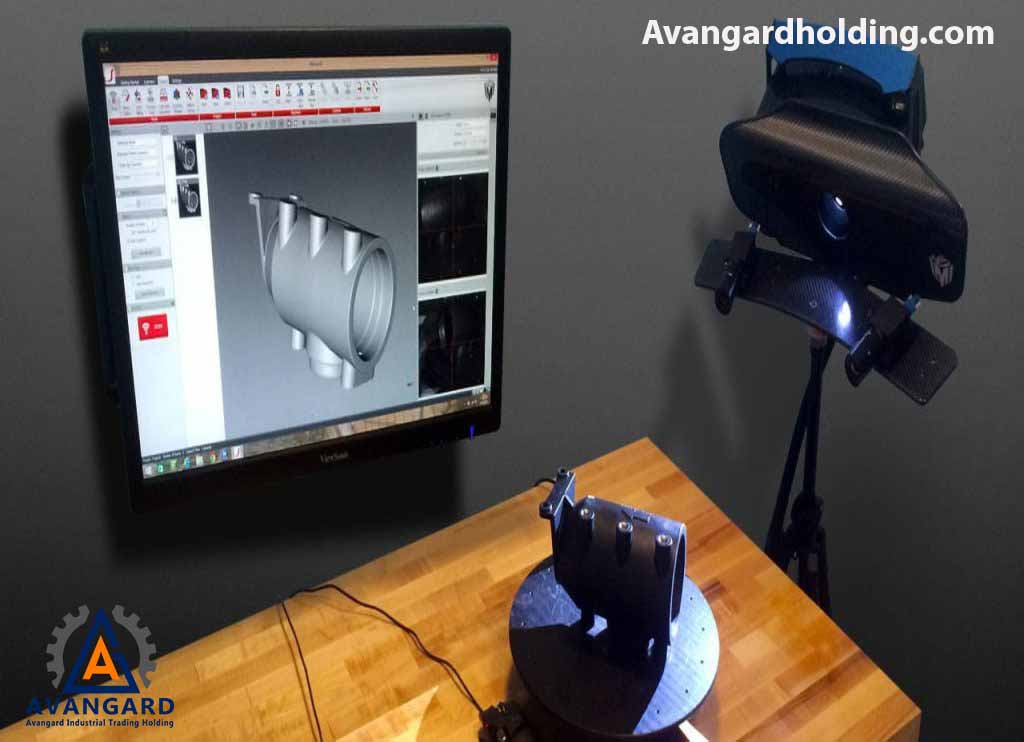
Non-Contact 3D Scanner
In the non-contact scanning method, scanning is performed using radiation and receiving reflections of the emitted beams. In optical technologies, parts and equipment with polished, transparent, or mirror-like surfaces may face challenges, and the best solution to address this issue is the use of titanium oxide powder. Two other common types of light-based 3D scanners used for 3D scanning include “structured light” and “laser scanning.” Structured light 3D scanners project patterns of light onto the object for imaging. Based on the changes in the light pattern, the shape of the part is determined, and a 3D mesh file or digital model is created. Laser 3D scanning uses a different approach. Laser triangulation scanning measures reflected lasers, which can be converted into 3D coordinates of an object and subsequently into a 3D mesh file. Most 3D scanners available on the market today use laser scanning technology. Some, like Structure.io or iSense, are simply a laser and sensor (transmitter and receiver) that you can install on your smartphone. Meanwhile, other 3D scanners use a small rotating platform to place the object on and scan it while it rotates. For example, the MakerBot Digitizer works this way.
Some advantages of using non-contact 3D scanners are as follows:
- A very fast and simple solution for creating a 3D file from a real-world sample.
- A simple way to scan samples with a high level of detail.
- Use in reverse engineering processes for immediate part production.
- Improving customization processes in the manufacturing of various tools and equipment.
- Reducing time and costs.
- High precision (10-5 microns).
- Dimensioning non-rigid parts such as foam, rubber, and other materials.
- The ability to compare the dimensions of manufactured parts with the original CAD model.
Simulation in the casting process is now widely recognized as an essential tool in product design and process development to improve the performance and quality of the casting process. One such tool used by Avangard Holding’s simulation team is the ProCAST software. ProCAST utilizes Finite Element Analysis (FEA) to simulate casting processes with high precision and ease of understanding solidification processes. Based on powerful Finite Element solvers and highly advanced options developed in collaboration with leading research institutes and industries, ProCAST provides an efficient and relatively accurate solution to meet the needs of the core industry, which is casting. Compared to the traditional trial-and-error method, using the powerful ProCAST software for casting simulation is a highly suitable solution for reducing production costs in foundries, shortening design and production timelines, and enhancing quality during the casting process. According to unofficial statistics, less than fifteen percent of companies worldwide use this powerful tool.
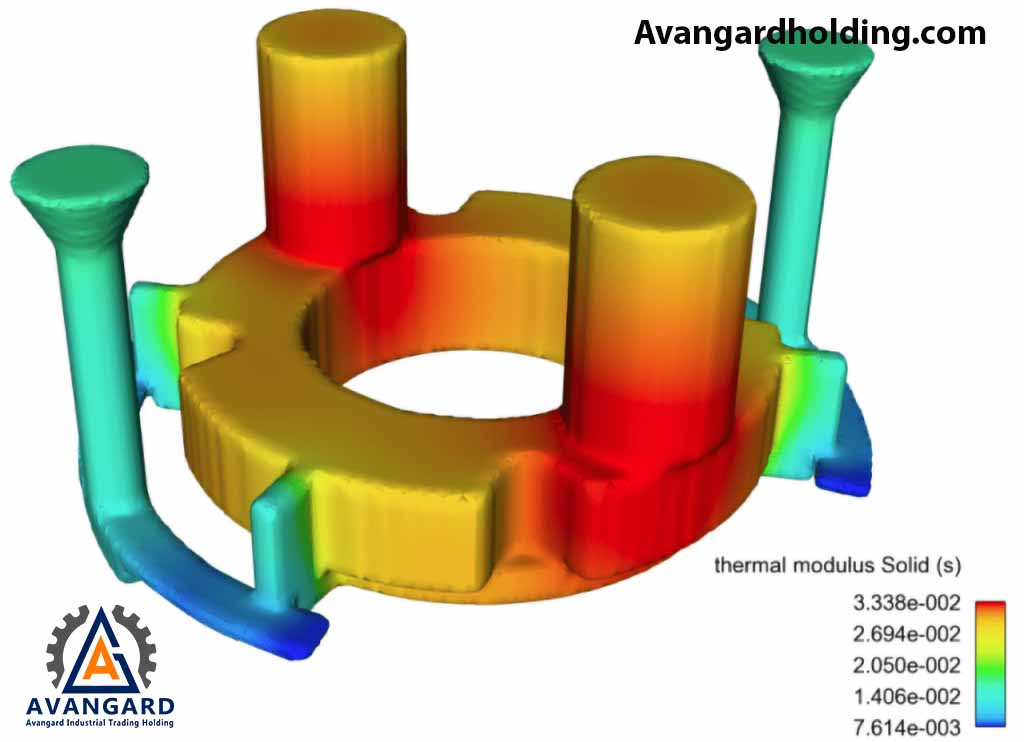
Using ProCAST provides a comprehensive software solution that offers precise predictive analysis of the entire casting process, including mold filling, solidification, microstructure, and thermal and mechanical simulations. It enables quick visualization of gate design effects and facilitates informed decision-making in the early stages of the production process.
By utilizing these powerful engineering tools, materials engineers combine graphical models and the actual casting process to provide critical feedback for optimizing designs. Ultimately, this ensures a reliable casting process for metallurgical engineers.
The simulation software (ProCAST) is used to satisfy and assure materials engineers of consistent quality and the delivery of defect-free cast parts. ProCAST simulation software is a tool for advanced and comprehensive casting processes, resulting from over twenty years of collaboration with reputable industrialists and leading academic institutions worldwide. Using ProCAST makes engineering and production easier throughout the process.
Initially, the focus was primarily on identifying and addressing hot spots in casting. With the advancement of computer-aided design (CAD) and numerical simulation software packages, metallurgical engineers are now able to make rapid changes in feeder selection and address potential defects with relative ease.
Today, ProCAST ESI allows for simultaneous analysis of heat flow, stress, and the estimation of all casting processes for all casting alloys, including defect detection, residual stresses, strain and distortion, microstructure, and mechanical property prediction. This method also addresses other production processes related to casting, such as heat treatment. Today, ProCAST is considered the most accurate, comprehensive, and powerful casting simulation method in the industry.
In the field of casting simulation, software such as ProCAST, Sut Cast, QuickCast, SolidCast, AutoCast, and MagmaCast are among the most important and high-quality simulation tools in the casting industry. Among these, ProCAST is the result of over twenty years of constructive collaboration with the casting industry. It is capable of performing fluid, stress, and thermal coupling analyses and also offers unique metallurgical capabilities for various casting alloys.
Drafting can be considered a type of communication language that provides precise and useful information about a part, machine, or structure. In general, drafting clearly introduces a design in engineering sciences.

Perhaps the most important step in manufacturing parts is their design and drafting. In engineering, when we intend to design a system (where a system refers to any interconnected set of mechanical parts and other components that work together to achieve a desired goal), we must first have a concept and idea of the parts and components that make it up. To bring the idea to fruition, we need to prepare the part drawings and assembly drawings (a drawing that shows the components in relation to each other and explains how the parts interact and how the system functions) as the first step.
Today, the design process in many industries, such as casting and modeling, automotive, aerospace, electronics, and more, is carried out through computers. This design method allows companies to first design their desired concept, then model and evaluate it. If the prototype model is approved, it is produced and put into operation.

In many countries, industrial design and all related fields have seen significant advancements. For example, the widespread use of computers and their peripherals in all industrial processes can be highlighted. These software tools enable designers to create products with high precision, minimal errors, and excellent quality. One of the fundamental challenges for novice designers in mold design and drafting is the inability to determine where to start the design process and which part of the mold to begin with. The accuracy of dimensions in mold design and drafting is of particular importance. If not adhered to, the user of the drawing cannot accurately calculate and extract the scales, and the simulation and execution of the design will face practical issues. In general, industrial design refers to determining the quantitative and qualitative characteristics of a product for industrial production. Commonly used software in this field includes AutoCAD, CATIA, and SolidWorks, with AutoCAD typically being used in 2D environments.
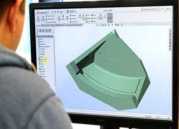
SolidWorks is the name of a widely used engineering software at Avangard Company, which is used for computer-aided design and can be installed on Windows. This software is provided and continuously developed by the French company Dassault Systèmes. SolidWorks is used by over 150,000 companies and 1.5 million engineers worldwide. The environments of this software include Part, Assembly, and Drawing.
The Part environment is used for designing and sketching desired components, the Assembly environment for displaying and assembling those components, and the Drawing section for creating printable versions and preparing engineering drawings. SolidWorks software includes practical and unique advantages that distinguish it from other similar software. Some of these features are as follows:
- Very simple user interface and ease of learning the software.
- High speed in design and assembly compared to other similar programs.
- Ability to interface with all CNC software and data analysis software.
The CATIA software was created and developed by Dassault Systèmes. Dassault Systèmes is a multinational software company based in France. It was established in the late 1970s for the development of fighter jets and later expanded into aerospace, automotive, shipbuilding, and other major industries. The initial name of this software was CATI, which was changed to CATIA in 1981.
Applications of CATIA Software
- Ability to fully design and model parts with complex appearances.
- Designing machining processes, production, and extracting G-code for CNC machining devices to facilitate the production of designed and analyzed parts.
- Capability to design molds and sheet metal models.
- Simulation display in CATIA software.
Modern CAD software in design uses vector-based mechanical design along with graphic-based design and can create the desired graphical image that represents the overall schematic of objects. Engineering software in this field requires more than just shape and schematics; detailed information such as dimensions, material types, processes, tolerances, etc., must be provided to the software. Among the advantages of this software is its use in large industries such as automotive, shipbuilding, aerospace, architecture, and more.
The responsibility for developing modeling, casting, prototyping technologies, as well as heat treatment processes for parts, lies directly under the engineering department of Avangard Company. One of the unique features of Avangard’s design and technology unit is the use of casting simulation software such as ProCAST, Sut Cast, MagmaCast, and others. Before the prototyping stage, the designed casting technology of the part is simulated and reviewed to ensure its accuracy and the absence of casting defects in the final product.