 فارسی
فارسی  Arabic
  Russian
Designing and modeling patterns is a complex process that requires high knowledge and experience.
The design and modeling team of Avangard Casting Parts Company is honored to rely on more than two decades of experience and high academic qualifications from reputable domestic and international universities for design and technology services, modeling, and casting more than ten thousand parts including pieces from various industries such as machinery manufacturing, automotive, mold making, oil and gas, petrochemical, power industries, cement industries, and mineral processing to serve you esteemed industrialists with the best and highest quality and the most suitable price for its design and modeling services.

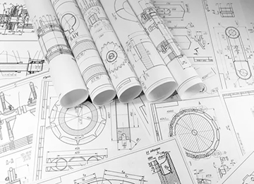
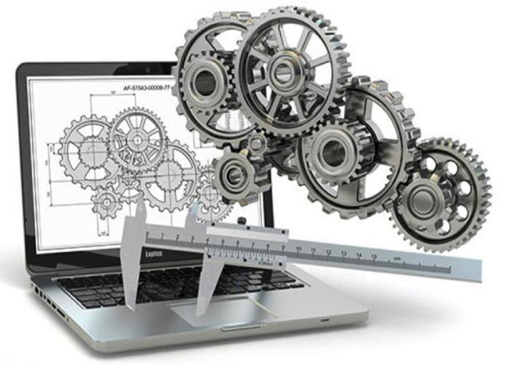
Drawing can be considered a type of language that provides you with precise and useful information about the part, machine, or structure. In general, drawing clearly introduces a design in engineering sciences.
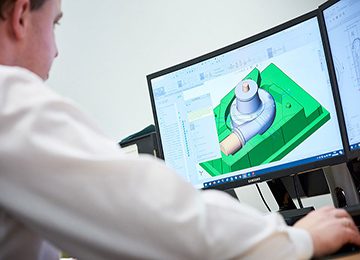
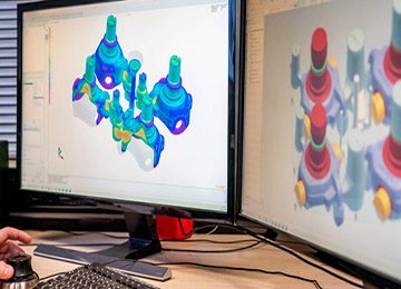
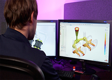
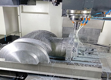
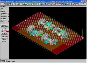
Today, model and mold design in the casting industry and also simulating the casting process and checking the quality before casting are of particular importance. Using this method achieves much better quality, reduces costs, and production time, which is why most complex casting parts are simulated by the Avangard’s technical team using engineering software.
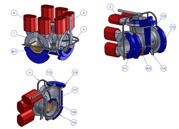
Perhaps the most important step in manufacturing parts is its design and drawing. In engineering, when we intend to design a system (the purpose of a system is any interconnected and attached set of mechanical parts and other components that in cooperation with one another fulfill the desired purpose), we must initially have a plan and idea for its constituent parts and components. In order to realize the idea, we need to prepare the part drawings and also the assembly drawing (a drawing in which components are shown in relation to each other, explaining the contact of components and the operation of the assembly) in the first step.
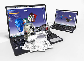
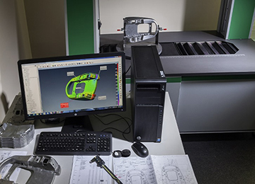
Today, the design process in many industries such as casting and modeling, automotive, aerospace, electronics, and others is done through computers. This design method allows design companies to initially design, model, and review their desired plan and proceed to production and exploitation if the model sample is approved.
In many countries, industrial design and all related matters have progressed significantly, such as the widespread use of computers and accessories in all industrial processes. This software allows the designer to design the product with high precision, minimal error, and very favorable quality. One of the main problems for template and drawing design by inexperienced designers is that they cannot determine from which part of the mold and section to start designing. The accuracy of sizes in template and drawing design is of special importance, and if not observed, the user of the drawing cannot calculate and extract dimensions accurately, and practically the simulation process and execution of the plan will have problems. In general, determining the quantitative and qualitative features of the product with the aim of industrial production is called industrial design. Application software in this field includes AutoCAD, CATIA, and SolidWorks, where AutoCAD is usually used in a 2D environment.
Today, the design process in many industries such as casting and modeling, automotive, aerospace, electronics, and others is done through computers. This design method allows design companies to initially design, model, and review their desired plan, and if the model sample is approved, they proceed to production and exploitation.
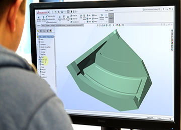
SolidWorks is a widely used engineering software in Avangard, which is employed for computer-aided design and can be installed on Windows. This software is provided and continuously developed by the French company Dassault Systèmes. SolidWorks is being used by more than 150 thousand companies and 1.5 million engineers worldwide. The environments of this software include Assembly, Part, and Drawing.
The Part environment is used for designing and drawing the intended parts, the Assembly environment for displaying and assembling those parts, and the Drawing section for printed versions and creating engineering drawings. SolidWorks software includes practical and unique advantages that distinguish it from similar software. Some of these features are:
- Very simple user interface and ease of learning the software
- High design and assembly speed compared to similar software
- Enabling interaction with all CNC work software and data analysis software
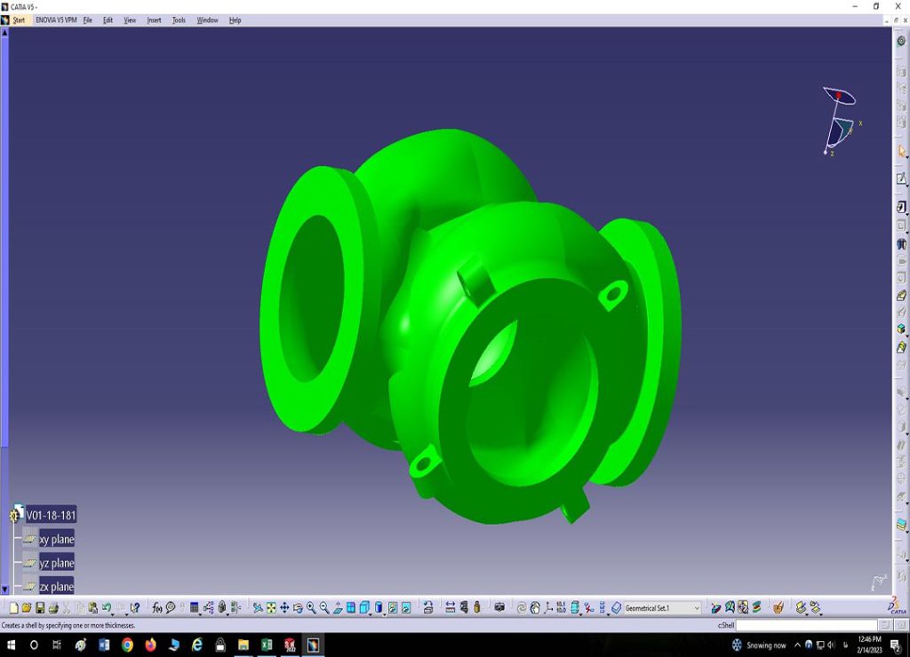
CATIA software is developed and extended by Dassault Systèmes, a multinational software company in France. Dassault Systèmes was originally created in the late 1970s for fighter jet development and continued to be used in aerospace, automotive, shipbuilding, and other major industries. The initial name of this software was “CATI,” which was changed to “CATIA” in 1981.
Applications of CATIA Software
- Comprehensive design and modeling of parts with complex appearances
- Machining process design, production, and G-code extraction related to CNC machine for facilitation in part design and analysis process
- Ability to design molds and sheet metal models
- Simulation display in CATIA software
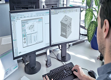
Modern CAD software in design uses vector-based graphics with mechanical design and can create the desired graphic image showing the schematic of objects. Engineering software in this field requires more than shape and schematics and must provide information such as dimensions, material types, processes, tolerances, etc., in detail to the software. The advantage of this software can be seen in large industries such as automotive and shipbuilding, aerospace, and architecture, etc.
The responsibility for developing modeling technology, casting, prototyping, and heat treatment operations of parts is directly under the supervision of Avangard’s engineering unit. One of the unique features of Avangard’s design and technology unit is the use of casting simulation software like ProCAST, Sut Cast, MagmaCast, etc., which during the prototyping phase, the designed casting technology of the part is simulated and reviewed to ensure its correctness and the absence of casting defects in the final product.
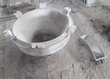
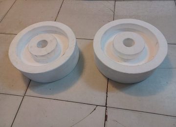
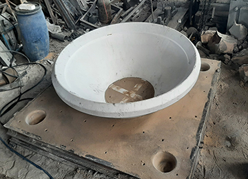
The design and construction of casting models and mold construction are among the prominent and important methods for producing and manufacturing metal parts.
Casting is identified in various fields of science, art, and technology. As much as casting progresses technologically and scientifically, in practice, it is still the experience, taste, and artistry of the model maker and caster that ensures the production of a healthy and defect-free part.
Before carrying out the casting process, modeling is needed. Casting modeling involves designing and constructing a casting model or pattern as a single or multiple-piece item.
Due to its critical role in the industry of manufacturing and designing metal parts, modeling in casting holds significant importance. Given that the design of casting models is a vital part of production processes through casting, we will discuss the design and construction of casting models further.
Avangard possesses an experienced and professional staff along with suitable tools for modeling, capable of designing, manufacturing, and producing any complex models and parts. Initially, when clients contact Avangard for casting model projects, typically three scenarios arise:
- In the first method, the contractor provides a 3D file of the template to us, which is to be made by our team.
- In the second method, the contractor holds a two-dimensional drawing of the part, and the 3D file is not available.
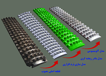
- In the third method, the contractor delivers the part to our company and requests the construction of its casting model, which will be further discussed in the reverse engineering section.
In all three scenarios, the Avangard engineering team examines the project subject and its quantitative and qualitative aspects and provides the client with an estimated cost and time for casting model construction. The proposed time for project execution varies based on the complexity of the models. At this stage, a contract for the project is signed between the client and Avangard, and the design and construction of casting models and molds begin by the technical team. Avangard, with its experienced team, will undoubtedly deliver the most accurate and highest quality model to you in the shortest time possible. Further in the text, we will review the details of inquiries extensively.
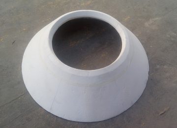
Casting pattern design is widely used due to the significant importance and application of casting methods in production processes. Approximately fifty percent of industrial machinery parts are produced using casting methods, such as parts with complex shapes or metals with low plasticity properties shaped by this method. Considering a significant portion of industrial products relate to casting parts, and the casting industries have played a significant role in technology development and production in industrial cities, the drawing and construction of casting models should be carried out in a manner compatible with the molding conditions and capabilities. Consequently, considering comprehensive design and modeling (Pattern Making), Avangard Engineering examines all services and processes before and after casting model design to ensure the production of high-quality, flaw-free parts.
A casting model is an object made from different materials and is used for creating the mold of the desired part in casting. Each of the different types of models is used in a specific place in the casting mold-making process. Without designing a casting model and mold, shaping casting parts is impossible. Therefore, it can be stated that modeling holds special importance in the production of various casting parts and is a crucial tool for mold making and casting. Casting models are categorized in various ways based on their specific features, which will be reviewed subsequently.
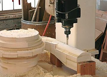
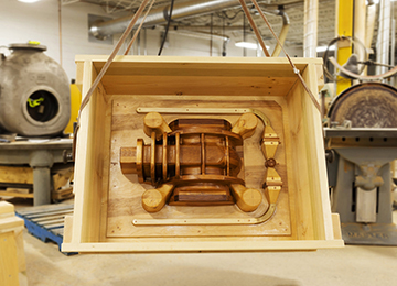
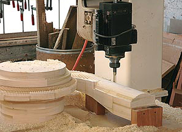
- Wooden Models
Wooden models are among the oldest and most widely used materials in modeling and also cheap in the modeling industry. Wooden models are suitable for low-run moldings, and the best woods used are pine, cedar, alder, maple, and walnut.
We will provide descriptions regarding the physical and mechanical properties and applications of some wood types used in modeling:
Understanding the mechanical properties of woods prevents mistakes in choosing the type of wood for different industries, including modeling. Some of the mechanical properties of wood include:
Splitting capability, bending capability, elasticity, tensile strength, compressive strength, torsion, bending, knee, shearing, and the effect of moisture on wood
*The most important properties and applications of some woods are briefly stated below.
-Alder Wood: It is soft and light, yellowish in color, has high laminating capability, and low elasticity, suitable for making small and medium models and molding.
-Maple Wood: It is hard with straight fibers, white in color. A special feature of this wood in the modeling industry is that it dries quickly after cutting and is very durable. This wood is used for making delicate and small models, furniture making, musical instruments, veneer making, etc.
-Walnut Wood: It is hard and strong, with superior physical and mechanical qualities. It is a well-working wood, very durable and resistant, with excellent capabilities for sawing, planning, polishing, varnishing, vibration, gluing, resistance to abrasion, resistance to fraying and fiber separation in water and humidity, etc. Its excellent nailing and screw capabilities make it widely used for home decoration, furniture making, gunstocks, and for small and precise casting models.

-Wild Black Cherry Wood: It is heavy, hard, and strong, excellent for cane making and precise modeling, etc.
-Linden Wood: Known as basswood, it is soft and light, grayish in color, with good bending capabilities and good drying properties, used for drafting tables, carving, modeling, etc.
-As moisture levels alter in wood, changes occur in its shape and volume, known as wood working; modelers should take sufficient care of the above points otherwise warping or twisting of the model is inevitable.
-Generally, all models are tried to be made with hard, durable, and strong woods. Obviously, for larger models, more suitable woods are selected, including red forest wood, oak, white forest, etc.
-For making high-quality small models at an affordable price considering their delicacy, woods like maple, ash, walnut, birch, etc., are used.
Avangard Holding, with over two decades of experience, presents high-quality models at a reasonable price and as quickly as possible to respectable casters.
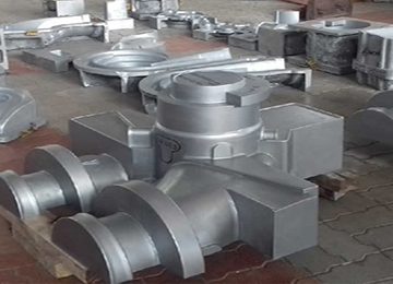
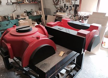
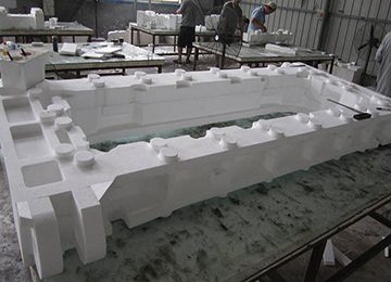
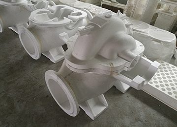
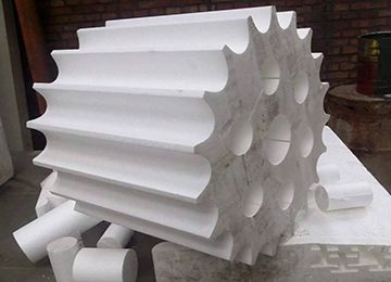
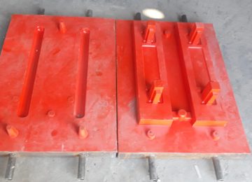
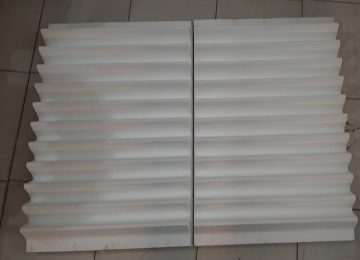
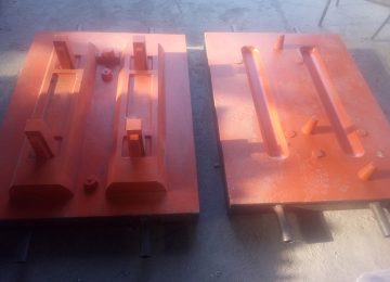
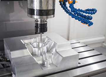
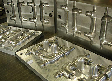
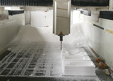
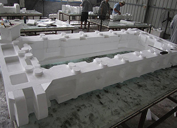
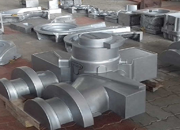
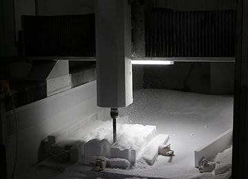
2. Metal Models These models are sometimes made directly from raw materials (ingots) using lathes, milling machines, CNC, etc., but are usually prepared via casting methods, and for their casting, wooden or styrofoam master (main) models are used. Metal models are among permanent models because they maintain their quality and dimensions after multiple moldings. Metal models are usually designed and made for moldings exceeding 20 pieces. The common materials for metal models are usually aluminum, steel, cast iron, etc. When creating primary (main) casting models, secondary contraction is also considered, typically applying a 1% shrinkage when converting wooden models to aluminum, as casting the metal model initially requires this, and if the model needs machining, an additional machining allowance or stock is also considered. 000 3. Disposable Models (Styrofoam – Polystyrene) Styrofoam: Used for melting models made from polystyrene. In the melting method, if a part has significant weight or if only one piece of that part is needed, and making wooden or metal models is not cost-effective, the styrofoam model method is used. In this case, the model is not removed from the sand mold, and when the melt reaches the mold, the model disappears, and the melt replaces it. In this method, there is no need for creating a core box, and after making the model, it is coated with a special coating material for that molten metal, whether cast iron, steel, or non-ferrous metals, and then the molding and casting process begins. To produce casting parts, a model is needed, where the part produced from the styrofoam model after applying the modeling contraction or shrinkage ratio equals the desired part in terms of dimensions and appearance. Avangard, with over two decades of modeling experience and casting parts production leaning on metallurgical science from top universities domestically and abroad, designs styrofoam models using specialized software like Catia, SolidWorks, and other specialized software, and produces all models three-dimensionally in the dimensions and sizes you need with the highest accuracy and most appropriate price using multi-axis CNC machines.
Some advantages of using styrofoam modeling:
-Very low cost of making styrofoam models compared to other models
-Ability to produce parts with negative draft without the need for modeling draft
-High precision in CNC machine building
-Very high speed of styrofoam model making
In conclusion, this type of model is very suitable for casting all sizes of parts, especially very complex, large, and heavy parts, which is economically very feasible.
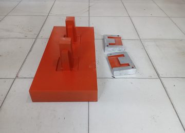
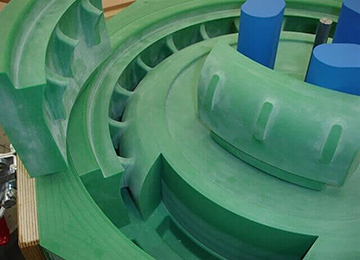
4. Composite Models
Models that are made from combining two or more materials, such as wood, plastic, epoxy resin (Araldite), silicone, etc.
- Single-Piece Casting Molds
- Two-Piece Casting Molds
- Multi-Piece Casting Molds
- Machine Models
If you want to produce a very large number of casting parts, it is better to use machine models. Since in this method, models are mounted on a special molding machine plate, known as machine plate models. These models are molded using semi-automatic or fully automatic machines, used in mass production.
- Manual models
These are models that are not feasible or cost-effective to machine, and are molded by hand inside a mold or sand hopper.
The construction of these models is such that they are molded and cast in a manual (traditional) way. And usually these parts have a non-uniform (broken) parting surface and have a lower speed than machine models.
The accuracy of making casting models has a great impact on the quality of the mold and the final part. Considering this, if the design and manufacture of casting models is not of appropriate accuracy and quality, it will ultimately lead to the production of parts with a low quality level. Therefore, before examining modeling in casting, we must first be familiar with the various methods of manufacturing industrial parts and molds, and finally examine the methods of molding, casting, and then designing and making casting models.
Metal Models:
These are also known as permanent models, where all parts of the model can be reused after multiple moldings and castings for further uses. For long-term moldings, these types of models made from alloys such as aluminum, cast iron, steel, etc., have a slightly higher production cost compared to other models.
Wooden Models:
These models, where all parts are made of wood, are usually most of the master models. These models are considered temporary because they change shape and dimensions after several moldings due to weather conditions, etc. If the casting frequency is under 20 to 30, this material is used for modeling and is recommended for medium to low quantity orders due to its considerably lower manufacturing cost than metal models.
Foam Models:
This is a disposable model, and after molding, it is destroyed. When we have a piece with great weight or only need one of that piece, and if making wooden or metal models is not economical, we use the technology of making polystyrene models.

| Polystyrene | Wood | Aluminum | Cast Iron | Property |
| Good | Excellent | Excellent | Excellent | Machining Capability |
| Weak | Weak | Good | Excellent | Abrasion Resistance |
| Weak | Weak | Good | Excellent | Strength |
| Weak | Good | Adequate | Weak | Repairability |
| Weak | Excellent | Excellent | Excellent | Corrosion Resistance |
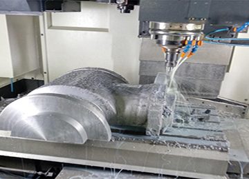
Today, using advanced equipment and precision tools, after obtaining the necessary plans and information about the desired part, the desired model is designed and constructed with 3D printers or CNC machines. Next, we will briefly explain the methods and tools for mapping the parts.
In this stage, after designing the scanned part, to compensate for any dimensional and structural changes that occur in the casting or modeling process, usually, additions such as shrinkage allowance, draft, machining allowance (casting weight), etc., are added to the design with the help of up-to-date design software, and the casting model is prepared.
Shrinkage Allowance (Contraction allowance / Shrinkage allowance)
One type of shrinkage is Volume shrinkage during solidification of steel, which a metallurgical engineer must calculate based on the material of the piece, through feeding it to compensate for the deficit to ensure the complete filling of the part’s core and prevent the formation of certain defects that could result from shrinkage during solidification. In this respect, elements such as tungsten and nickel have a negative impact, while others like manganese, chromium, silicon, and aluminum have a positive impact on shrinkage.
Another type is linear shrinkage, which must be considered by the model designer based on the material of the part: for example, approximately one percent for aluminum and cast iron, about 2 percent for simple carbon steels, about 2.6 percent for stainless steel parts, and about 2.8 percent for Hadfield manganese steels.
Once pouring is done within a sand mold or die-cast, and from the moment the piece begins to solidify until it completely freezes and reaches room temperature, it will experience linear shrinkage. The person responsible for cast model making should consider this shrinkage and make the model slightly larger. Typically, this shrinkage ranges from 0.5 to 3 percent. In reality, the amount of shrinkage is variable based on the mold system, and can vary among different casters based on adhesive type, sand type, and amount of sand compaction. In this regard, Avangard modeling, utilizing precise engineering calculations and the experience of casting more than 10,000 pieces across varied industries, applies the correct linear shrinkage.
Draft Allowance (Draft allowance)
To prevent friction of vertical surfaces against the split line, all these surfaces are made with a draft so that the model can be easily removed from the mold.
Draft calculation and application are done in the following three ways:
1-Positive Draft
2-Decreased Draft
3-Medium Draft
In the positive draft method, the amount of draft is added to the model dimensions, thus increasing the part’s weight slightly, which Avangard modeling group applies the appropriate draft according to the previously explained three types based on the part’s function during the design phase.
Machining Allowance(Finishing or Machining allowance)
Surfaces obtained in sand castings usually have low surface quality, so many parts undergo machining or grinding to improve surface quality. During machining processes, some metal is removed from the part. To compensate for this, a machining allowance is included on the casting model. The amount of machining allowance depends on the material, the dimensions of the casting piece, production volume, molding method, etc.
Additionally, sometimes appendages or extensions are applied for mounting on machining devices, which are removed after machining.
The amount of machining allowance or extra load depends on the quality of casting and the sensitivity of the part to operations such as turning, grinding, drilling, etc. Generally, the minimum amount of additional load for surfaces needing machining is over three millimeters, and given the fact that thickness increase will raise the final cost of the part, measures could be taken according to the alloy type and various production methods such as die-casting and lost-wax casting to minimize machining and other processes.
Shake Allowance(Shake allowance)
Generally, in removing the model from the mold, a shake or vibration is induced to the model by the molder for ease of removal. During this process, the final cavity enlarges. To compensate for this, the model dimensions must be reduced. There is no standard measure for this allowance as it heavily relies on the worker. This allowance is negative, and a common method to mitigate this negative allowance is increasing the positive draft. A shake on the model will enlarge the mold cavity, thus enlarging the final cast piece.
Distortion and Complexity Allowance(Distortion allowance)
During the cooling of the mold, stress induced by differential cooling rates in different parts of the object could cause distortion. This is more prominent when the mold has a high length-to-width ratio. This can be minimized by an initial deviation of the model in the opposite directions.
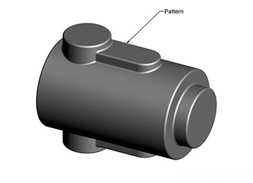
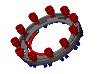
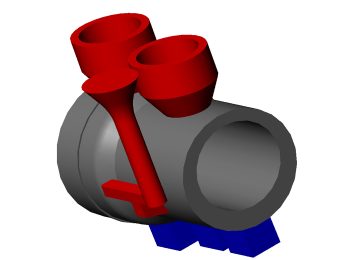
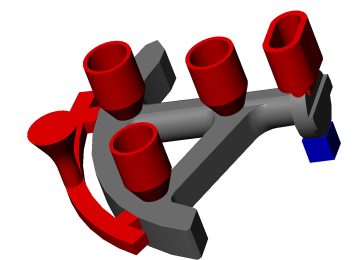
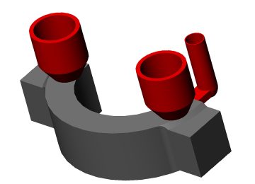
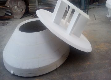
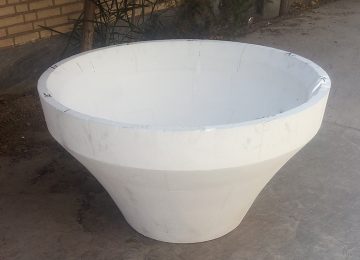
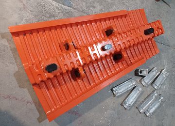
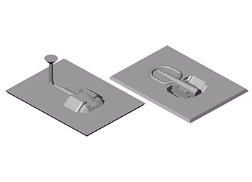
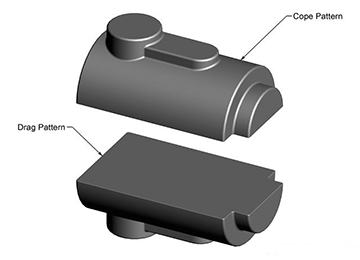
Based on the shape and complexity of the part and the design and manufacturing technology, the designer determines a separation line for the part, typically dividing the part into two sections, and then proceeds to construct the model.
After producing and machining the model components, each component is placed on a board, and after precise marking, the guide pin location on the board is determined.
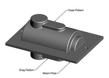
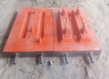
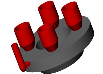
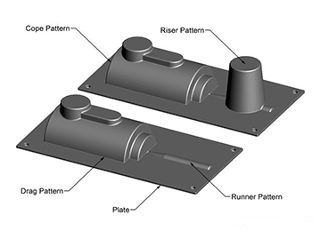
In the final stage, the installation of the gating system and the installation of the model on separate model boards are done under the headings of lower and upper bands.
In another method, known as Match Plate Pattern, upper and lower parts together called cope and drag portions are constructed. These parts are mounted on both sides of a board, making it possible to quickly separate the models from the molding materials. Another method in Patterning Cast Molding is designing a unilateral plate model. These plate models are also known as cope and drag pattern and are primarily used for large casting dimensions. In these types of patterns, both sides are mounted on separate board models. Indeed, these types of models allow connection to vertical or horizontal machines and mold using molding materials.
Avangard Holding, with over two decades of experience and advanced education from prestigious domestic and foreign universities, designs and produces over ten thousand parts for industries such as machinery, automotive, mold making, oil and gas and petrochemical, power plant industries, and cement and material processing industries. We guarantee to provide you, respected industrialists, with the best, highest quality services at the most appropriate price.
Reverse Engineering is a method whereby dismantling the components of a product or object and assembling it, we obtain important data about how the product is designed. Reverse Engineering is a precise method for reaching current technology and existing products.
In this process, specialists from various fields of basic and applied sciences, such as mechatronics, metallurgy, polymer chemistry, mechanics, physics and optics, electronics, and others, form highly specialized groups to fully familiarize themselves with the implementation method of a product whose technology template is advanced. By using advanced equipment and facilities, along with precise laboratory devices, and proper organization of research and development structures (R&D), they strive to obtain the details, documents, and design maps of the targeted product. After prototyping (Prototyping) and semi-industrial manufacturing (Pilot Plant), and if possible, the above product is produced following the technical standards of the initial product.
As mentioned, using the reverse engineering process for developing or third-world countries is a very suitable method for accessing technology, growth, and advancement. These countries, which are very weak in many technologies, alongside methods and policies of obtaining technical information, have found reverse engineering the best method of accessing technology. They attempt, using reverse engineering methods, to retrieve knowledge and technical information of available components, operation mechanisms, and other important information. Alongside employing direct engineering methods (Forward Engineering) and methods of preparing and manufacturing parts, facilities, testers needed for the assembly line, and manufacturing like molds, gauges, and fixtures, proceed to establish an advanced and equipped factory to produce the above products.
Reverse engineering can also be used to eliminate defects and enhance the features and advantages of existing products. For example, in the United States, reverse engineering has been used by Ford Motor on General Motors company products and vice versa, to maintain competitive conditions and remedy product defects.
At Avangard Holding, for modeling and casting parts services via reverse engineering are conducted as per the following:
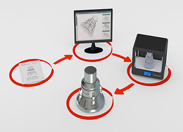
When a part is brought in for casting purposes at the company, depending on its documentation, it will undergo the following processes.
Initially, the part’s coordinates are prepared by scanning, and then a two-dimensional drawing and a three-dimensional model are created based on the cloud points.
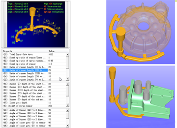
The casting model drawing is prepared based on the drawing and model of the part and considering the explanations and considerations presented initially, and depending on the importance of the part, a casting simulation process is presented using numerical methods to calculate the quality of parts given the mold filling, cooling, and solidification, and a quantitative prediction of mechanical properties, thermal stresses, and distortion.
Pre-production simulation precisely analyzes and describes the part’s quality.
The benefits of simulation go beyond reducing initial prototyping before production, as the precise design of the casting system results in energy, material, and tooling savings. Analysis and simulation of the casting process using various software have advantages such as:
- Continual productivity improvement
- Increased accuracy
- Reduction of scrap volume
- Cost reduction
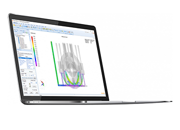
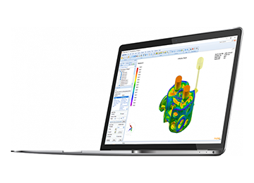
The casting process simulation is conducted using software such as ProCAST and sut cast.
The ProCAST software is a powerful computer-aided engineering software for finite element method (FEM) analysis in the market. This software is a product of the ESI Group in France, using the finite element method for modeling casting processes. It features capabilities like flow analysis, thermal analysis, and stress analysis of casting parts, thereby minimizing defects resulting from pouring (e.g., gas entrapment or turbulence) and solidification (e.g., porosity or gassy).
The sut cast software is also one of the most powerful tools for visualizing, modeling, analyzing, and optimizing casting processes. This software simulates the molten metal from various conventional casting alloys into sand or permanent molds.
SUTCAST also simulates the mechanical properties (hardness, tensile strength, and yield strength) and microstructure of casting.
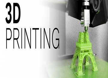
In low volumes, the initial prototype of the model is prepared via rapid prototyping methods, such as 3D printing or making a foam model using CNC, and in mass production of models, aluminum or cast iron casting and machining are prepared with high accuracy and quality.
Material and alloy selection is based on customer analysis or obtaining a sample from the original part, analyzing by quantometer device, determining microscopic structure, and also specifying mechanical properties of the part, or material selection using CES software. The modeling process and the appropriate casting method are performed accordingly.
Some applications of reverse engineering include:
- Recreating custom antique objects
Reverse engineering is the best and most accurate way to create an object for which there is no data or where you only possess the item or object itself. For example, assume the original shape of a product. When a design is created for it using software, ensuring the designed model matches the original sculpture can be challenging. However, it makes recreating the product straightforward because the physical model of the product is your source of information for computer-aided product design.
- Completing and enhancing parts
A part or product may need upgrade and enhancement. If you can’t find a substitute in the market for the desired part, you can use reverse engineering to create a copy of the original product design. Not only can you analyze the parts for failures, but you can also redesign them for increased thickness or use more durable materials.
- Creating CAD models
In reverse engineering, code files can be studied as a reference for the future. This way, you can utilize computer-designed models for testing production stages and achieving methods to increase efficiency. This technology helps engineers gain accurate and precise information, saving their time.
- Identifying product vulnerabilities
Reverse engineering assists in identifying defects and errors in the product. When examining an existing product using reverse engineering, you can identify defective parts and ensure user safety and comfort. Attention to the digital files created by this process clearly shows flaws and shortcomings, allowing you to plan for repairs or replacements.
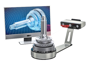
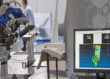
A 3D scanner is a tool that allows obtaining information regarding the appearance and external representation of a part. This technology is one of the simplest and fastest ways to achieve information about the appearance and shape of a product. Eventually, 3D scan data is transformed into a 3D model of the desired part. A 3D scanner is a device that analyzes an object or an item in the real world to obtain information regarding features such as color, dimensions, and appearance. The obtained information is used for creating a 3D model. Indeed, 3D scanner devices are powerful tools in game and film production, with other various applications in prototyping, artificial limb fabrication, documentation, industrial design, and more. The result is a 3D file in the computer that can be saved and edited, representing an object, environment, or person. Avangard’s design and engineering team offers optical dimensioning services and, utilizing the most advanced industrial digitizers and optical OCMMs, provides 3D scanning and dimensioning services to industrial sets without limitations on material, size, and dimensions. Through 3D scanning, we can achieve more accuracy, speed, and reliability for critical projects compared to other inspection methods.
Contact 3D Scanner
These scanners collect relevant information through physical contact and touching the part in question. In the contact method, the part in question is polished to a specific level of surface smoothness so that it can be scanned.
Contact 3D scanners use three different mechanisms to scan an object in 3D:
This scanner consists of an arm whose end slides on a rail. This type of contact 3D scanners is suitable for 3D scanning of profiles with a flat surface or surfaces with simple convexity.
A rigid arm consisting of several joints and precise angle sensors that determine the position of the end of the 3D scanner arm by calculating the angle of each joint. This part of 3D scanners is suitable for 3D imaging inside holes and parts of objects that have little access.
A combination of the two types of contact 3D scanners mentioned above. This type of contact 3D scanner consists of an articulated arm that slides on a rail. This contact 3D scanner is suitable for 3D imaging of large objects with internal cavities and overlapping surfaces.
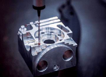
CMM
CMM, which stands for Coordinate Measuring Machine, is a type of contact 3D scanner that is mostly used in industry and can be very accurate. The problem with the CMM 3D scanner is that in order to scan an object in 3D, it must be in contact with it. So the process of 3D scanning an object with a CMM can cause changes or even destruction of that object. This can be very important and vital. Imagine trying to scan delicate objects such as ancient artifacts and antiques with a contact 3D scanner! Another disadvantage of the CMM is that it is slow compared to other tools. The physical movement of an arm with a CMM probe attached to the end can be very slow. The fastest CMMs can operate at only a few thousand hertz. Unlike contact 3D scanners, optical 3D scanners, such as laser 3D scanners, can operate at 10 to 500 kilohertz.
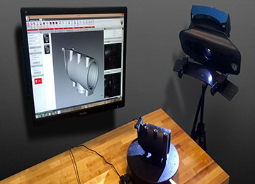
Non-contact 3D scanner
In the non-contact method, a scan is prepared by using a beam of light and receiving the reflection of the emitted rays. In optical technology, equipment and parts with transparent and polished surfaces may encounter problems, which use titanium oxide powder to solve this problem.
There are two common categories of 3D scanners that are based on light for 3D imaging: the first is called “laser scanning” and the second is called “structured light”. 3D scanners using the structured light method cast patterns of light on the object in order to capture images. According to the changes in the light pattern, it determines the shape of the part and creates a 3D mesh file or a digital model.
Laser 3D scanning uses a new method. Angular laser scanning measures reflected lasers, which can be converted into the 3D coordinates of an object and thus into a 3D mesh file.
Most 3D scanners currently use laser scanning technology. Some, like Structure.io or iSense, are simply a sensor and laser (transmitter and receiver) that you can easily install on your smartphone. While other 3D scanners use a small rotating disk that you place your object on and scan it as the part spins on it. For example, the Makerbot digitizer works this way.
Advantages of using a non-contact 3D scanner:
- A quick and easy way to create a 3D file from a real sample
- An easy way to scan samples with a high level of detail
- Use in reverse engineering processes for the production and manufacture of parts in an emergency
- Optimization of customization processes in the manufacture of various accessories and equipment
- Reduction of time and costs
- High dimensional accuracy (5-10 microns)
- Ability to measure the dimensions of non-rigid parts (rubber, sponge, etc.)
- Ability to compare the dimensions of the parts produced with the original CKD model
Simulation of the casting process is now accepted as an important method in product design and process development to optimize performance and enhance the quality of castings. One of the tools used in Avangard’s simulation suite is the ProCAST software. ProCAST uses finite element analysis (FEA) to simulate casting processes with high accuracy and ease of understanding the solidification processes. ProCAST, based on very strong finite element methods and specific advanced items prepared with leading research institutes and industries, offers an accurate and efficient method and solution to meet the needs of the casting industry. Compared to traditional trial and error methods, ProCAST is the main solution for reducing production costs, decreasing design time for mold development, and optimizing the quality of the casting process. Less than 15% of the global industries possess this precise and valuable tool.
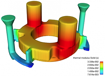
Using ProCAST provides a comprehensive software method that offers precise predictive analyses of the entire casting process, including mold filling, solidification, microstructure, and thermal and mechanical simulations, allowing rapid visualization of design effects and facilitating suitable and precise decision-making in the early stages of the production process.
By utilizing ProCAST software, specialists combine the reality of the casting process and the graphical model to provide the best report for design optimization. Ultimately, it ensures a reliable and accurate casting process for metallurgical engineers.
In ProCAST, we use this software to increase your satisfaction with high-quality and defect-free cast piece delivery. The ProCAST tool is an advanced and complete casting process simulation software based on comprehensive and precise collaboration with academic institutions and industrial companies worldwide. Using ProCAST, design and production are carried out more efficiently and accurately throughout the process.
Software Development Process
Initially, the focus was mainly on identifying and eliminating hot spots in casting. With the advancement of computer-aided design (CAD) and numerical simulation software packages, the metallurgical engineer can quickly make changes in feeder selection, eliminating potential defects with relative ease.
Today, ProCAST ESI allows simultaneous analysis and evaluation of heat flow stress and estimation of all casting processes for all casting alloys, including defect detection, residual stresses, strain and distortion, microstructure, and mechanical property prediction. This method also addresses other production processes related to casting, including heat treatments. Today, ProCAST is considered the most accurate, comprehensive, and powerful casting simulation method in the industries.
In the field of casting part simulation, ProCAST, Sut Cast, QuickCast, SolidCast, AutoCast, and MagmaCast are considered some of the most important casting simulation software. Among them, ProCAST results from more than 20 years of a constructive relationship with the casting industries, capable of fluid, thermal, and stress analyses, and additionally has unique metallurgical capabilities for casting alloys.
Avangard Engineering Holding, with over two decades of experience and high academic qualifications from reputable universities inside and outside the country, and the design and technology of over ten thousand parts, including machinery, automotive, mold-making, oil and gas and petrochemical, power industries, and cement and mineral processing industries, assures you, dear industry professionals, the best and highest quality and most suitable price services for modeling, simulation, and ultimately casting.
